PGC5007
PGC5007 Operating Instructions 3 Operation
9 OI/PGC5007-EN, Rev C
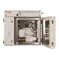
Figure 3.4 illustrates a typical flow diagram for the dual vapor version.
CARRIER
SUPPLY
NO. 1
SV
P
A
B
HEATER
AIR ADJ
VAPOR
SAMPLE
VALVE
2
PI
HEATER
SPLITTER
VENT
FURNACE
BURNER
BLOCK
COLUMN
NO. 2
COLUMN
PRESSURE
ADJ
DETECTOR
PMT
HOUSING
FPD
ENCLOSURE
ISOTHERMAL
OVEN
CELL
VENT
NO
. 1
COLUMN
PRESSURE
ADJ
SUPPLY
AIR
CAPILLARY
TUBING
EPC
ZONE
1
H2 RESTRICTION
ORIFICE
FLAME
ARRESTORS
CAPILLARY
TUBING
CAPILLARY
TUBING
RELIEF
VENT
SPLITTER
VENT
ADJ
EPC
ZONE
2
EPC
ZONE
3
H2
ADJ
PS
H2
SUPPLY
EPC
ZONE
4
CAPILLARY
TUBING
CAPILLARY
TUBING
CAPILLARY
TUBING
VAPOR
SAMPLE
VALVE
1
SAMPLE
INPUT
Fig. 3.4. Dual Vapor Version Flow Diagram
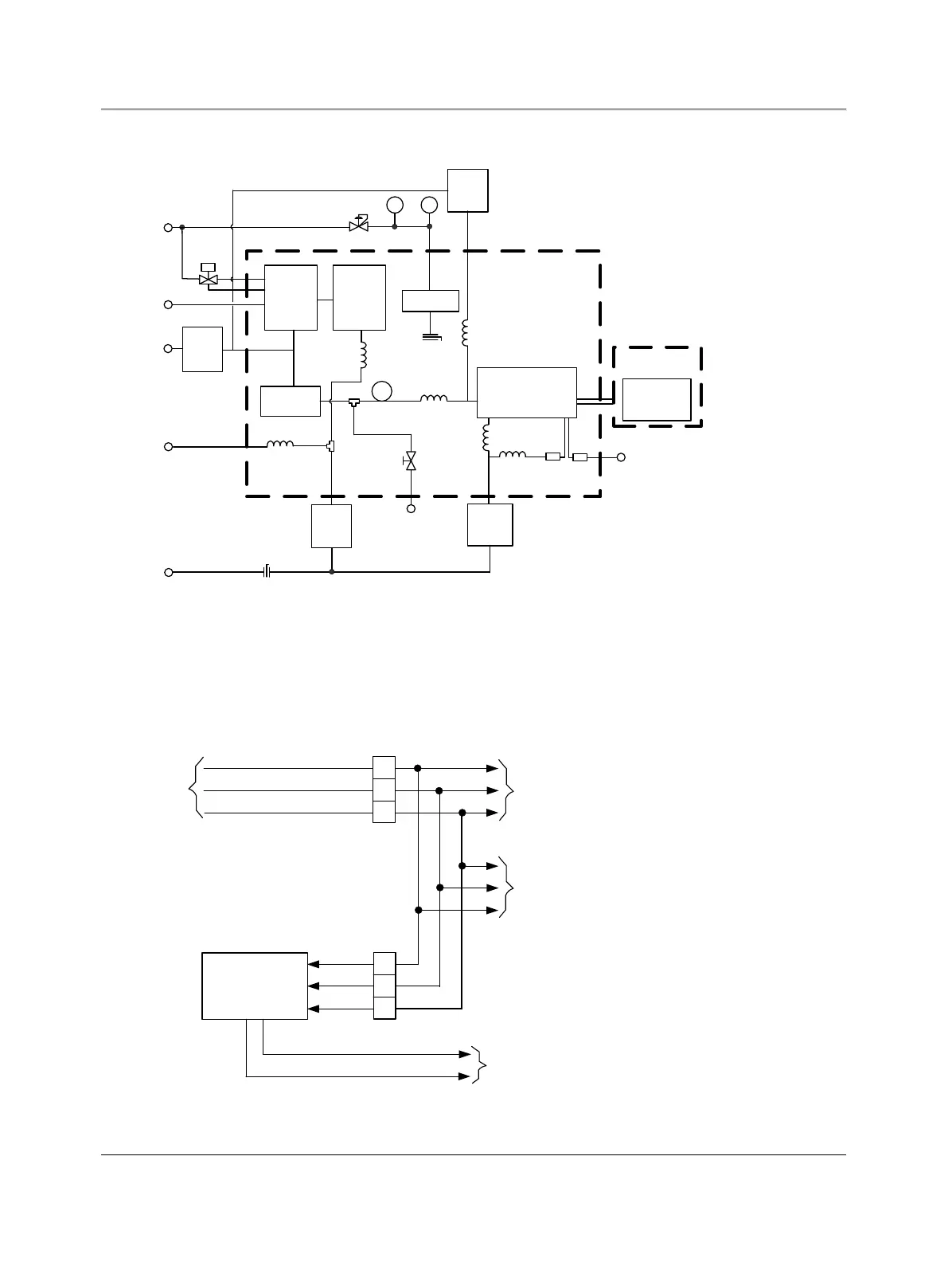
3.3 Power distribution
The Fuel Sulfur Analyzer utilizes the same power distribution circuits as the standard PGC5000 analyzer. In addition, the
PGC5007 has an autoformer to provide 40 VAC power to the furnace located within the furnace Exd enclosure in the oven
section of the analyzer (see Figure 3.5).
115
to
230 VAC
(Not Filtered
or Conditioned
)
1
3
2
J
1
Hot
Neut
Gnd
6
4
5
J7
Autoformer
VAC
#1
(to heaters
)
VAC
#2
(to electronics)
40 VAC to
Temp Controller
Fig. 3.5. Input Power Distribution