PGC5007
PGC5007 Operating Instructions 7 Detector repair
35 OI/PGC5007-EN, rev C
7 Detector repair
It is the customer’s responsibility to ensure that the area is safe and and hazard-free, and will remain so
the entire time the analyzer is open. This responsibility includes ensuring adequate ventilation in
analyzer shelter and obtaining proper work permits, etc.
7.1 Replacing the photomultiplier assembly
1. Remove power from the analyzer.
2. Allow all temperature zones to cool, maintaining flow while the columns are cooling.
3. Turn off carrier, sample and air to the analyzer.
4. Open the side door of the Electronics Enclosure.
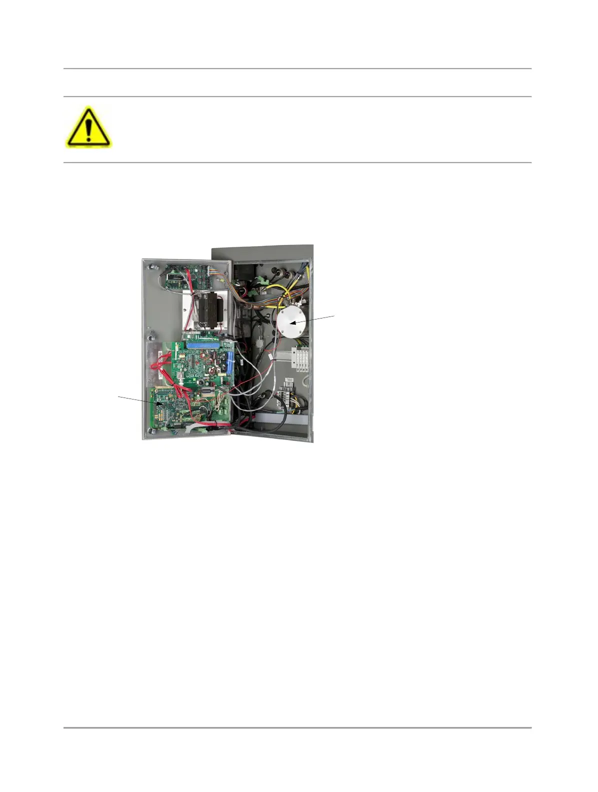
5. Disconnect the cables to the Photomultiplier Assembly (see Figure 7.1) and set them aside.
Photomultiplier
Tube
DTC PCB
Fig. 7.1. Electronics Enclosure
6. Remove the four bolts securing the Photomultiplier Assembly (PMT) to the analyzer, being careful to retain the bolts to
reinstall the PMT.
7. Carefully pull the PMT straight out of the analyzer, supporting the Burner Block to allow you to remove the PMT.
8. To reinstall the PMT, slide the PMT so that the tube just enters the oven.
9. Place the Burner Block so that its tubing nut aligns with the PMT light pipe. The Burner Block nut must form a straight line
with the PMT light pipe to allow them to fit together.
10. Support the Burner Block and slide the PMT the rest of the way into place.
11. Install and tighten the four screws holding the PMT in place.
12. Reconnect the cables to the PMT.
13. Close the Electronics Enclosure door.
7.2 Replacing the burner block
1. Remove power from the analyzer.
2. Allow all temperature zones to cool, maintaining flow while the columns are cooling.
3. Turn off carrier, sample, and air to the analyzer.
4. Open the Electronics Enclosure side door.
5. Locate the DTC PCB (see Figure 7.1).