PGC5007
PGC5007 Operating Instructions 7 Detector repair
36 OI/PGC5007-EN, rev C
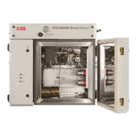
6. Disconnect the heater, thermocouple and temperature sensor leads from the DTC PCB (see Figure 7.2).
Fig. 7.2. DTC PCBConnections
7. Untie the cabling to ensure it can be removed from the Electronics Enclosure.
8. Open the isothermal oven door.
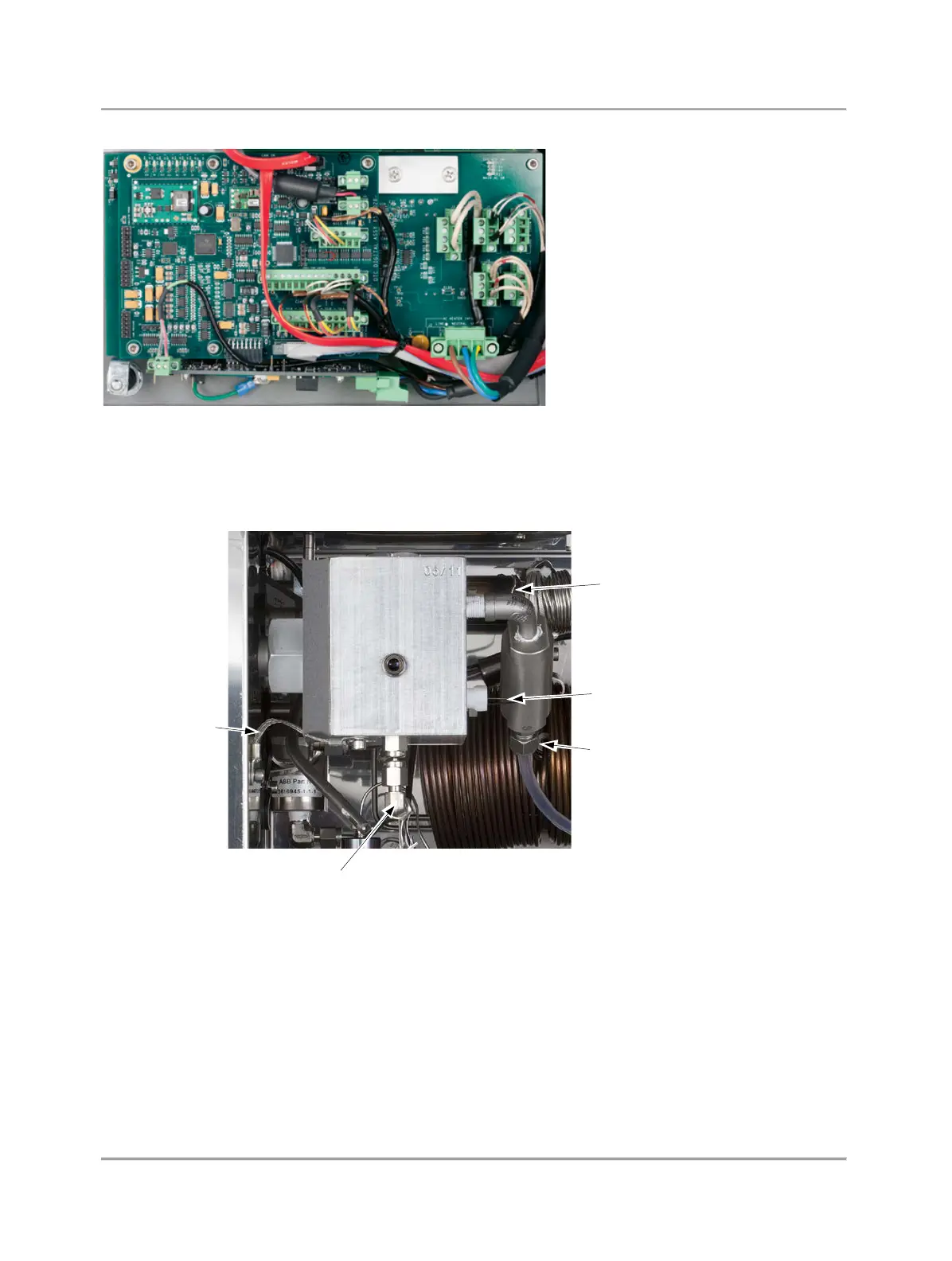
9. Disconnect the sample line from the Burner Block (see Figure 7.3).
Ground/Retaining
Strap
Disconnect Vent
Connection Here
Sulfur Addition
Module
upper connection
Sulfur Addition
Module
lower connection
Jet
Fig. 7.3. Burner Block
10. Disconnect the vent line from the Burner Block breather.
11. Disconnect the hydrogen (H2) and carrier lines from the Burner Block.
12. Disconnect the Ground/Retaining Strap from the Burner Block.
13. Slide the Burner Block off the Photomultiplier Assembly light tube (at the same time, the conduit will slide out of the
Electronics Enclosure) and remove the Burner Block from the oven. You may need to assist the wiring through the
enclosure.
14. When you install the new Burner Block, support the block and pass the wiring through the opening into the Electronics
Enclosure.
15. Carefully align the Burner Block and conduit, and slide the tubing nut over the light tube from the PMT.
16. Reconnect the Ground/Retaining Strap.
17. Reconnect all lines removed when you removed the Burner Bock.
18. Route the cabling through the Electronics Enclosure and reconnect the wires to the appropriate terminals on the DTC PCB.