PGC5007
PGC5007 Operating Instructions 6 Liquid sample valve repair
33 OI/PGC5007-EN, Rev C
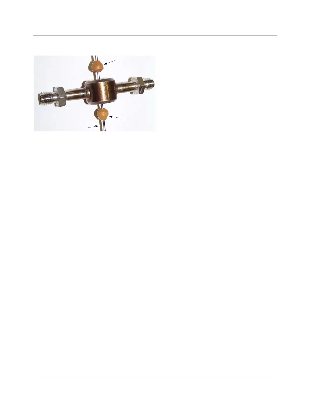
17. Slide the first cleaned seal over the stem using the “A” end of Seal Insertion Tool TL-791A006B. The 30° angle (pointed
end) of the seal must face the Belleville springs. Figure 6.4 shows the orientation of the seal.
Figure 6.4. Installing the Stem Seals
18. Slide the cleaned sample chamber over the stem onto the seal.
19. Slide the second cleaned seal over the stem using the “B” end of Seal Insertion Tool TL-791A006B. The 30° angled
(pointed end) of the seal faces out, away from the sample chamber. Figue A-14 shows the orientation of the seal.
20. Lightly lubricate the threads on the body.
21. Retract the stem until it is flush with the front of the seal.
22. Screw the body into the flange against the vaporizer chamber until tight.
23. Push the stem into place.
24. The sample chamber should be loose in the assembly at this point. If not, back out the tensioning nut until the sample
chamber is loose. Use the end of a 0.156 Allen wrench in the slot of the tensioning nut to adjust to the point of
eliminating the longitudinal play of the sample chamber.
25. Tighten the tensioning nut in 24 1/4-turn increments (6 turns total) to load the seals.
26. Lightly lubricate the inside bore of the cylinder.
27. Align the fittings on the cylinder with the sample chamber tubes, or with air lines if servicing.
28. Slide the cylinder onto the piston and the body.
29. Install two cone point set screws into the cylinder and tighten into the groove on the body.
30. Reinstall tubing to the LSV, being careful to connect each line to the proper connection on the LSV.
31. Close the isothermal oven door.
6.4 Removing the LSV from the analyzer
1. Remove power from the analyzer.
2. Allow all temperature zones to cool, maintaining flow while the columns are cooling.
3. Turn off carrier, sample, and air to the analyzer.
4. Open the isothermal oven door.
5. Remove the furnace cover as described in “Removing the Furnace Cover.”
6. At the right side of the furnace, remove the carrier line as follows (reference Figures 5.3 and 5.4):
a. Use the ABB Tee wrench to hold the nut.
b. Using a 9/16-inch wrench, disconnect the line just outside the furnace tube.
7. Loosen the nut, on the furnace housing, that retains the vaporizer
8. Label all connections to the Liquid Sample Valve.
9 Disconnect all tubing from the Liquid Sample Valve.
10. Mark the analyzer and flange to ensure the flange is reinstalled in the correct orientation.
11. Remove the four screws holding the flange to the side of the analyzer.
12. Remove the Liquid Sample Valve from the analyzer. The insulation and insulation retainer may move during LSV removal;
retain them for later installation.
13. Close the isothermal oven door.
6.5 Installing the LSV on the analyzer
1. Open the isothermal oven door.