PGC5007
PGC5007 Operating Instructions 3 Operation
7 OI/PGC5007-EN, Rev C
3 Operation
3.1 Startup
When the power is applied to the Smart Oven™, all components receive power.
Temperature settings are application dependent and are determined by the factory. Temperature settings for heated
component zones can be found in the Data Package shipped with the analyzer. This information should be used as a reference
during setup and startup, and when troubleshooting and calibration are performed. If adjustments need to be made, they
should be made according to the information in the Data Package.
Allow adequate time for the isothermal oven and furnace to heat to the proper temperature levels. Check the oven
temperature at the Setup Tab screen. The FPD will not ignite unless it is at operating temperature.
When you perform the time cycle check, verify isothermal oven, furnace, liquid sample valve (if applicable), and detector
temperatures on the Setup Tab screen with Data Package information. (These temperature settings are made in the factory
and should not need adjustment.)
3.2 Setting flows
When making any flow adjustments, allow time for the system to respond to the change and stabilize. It is recommended that
no measurement be taken for 30 seconds after any flow adjustment. Three consecutive measurements should be taken at 30-
second intervals to verify flow stability.
Sample splitters are employed when the volume of the injected sample is so large that it might overload the column or the
detector. To overcome this, the amount of sample is reduced by a sample splitter tee. By adjusting the flow of the carrier gas
from the splitter, the amount of sample entering the column is reduced
.
Before applying heat to the oven and oven components, ensure carrier is turned on to allow flow through
the columns while they are heating to prevent damage to the columns.
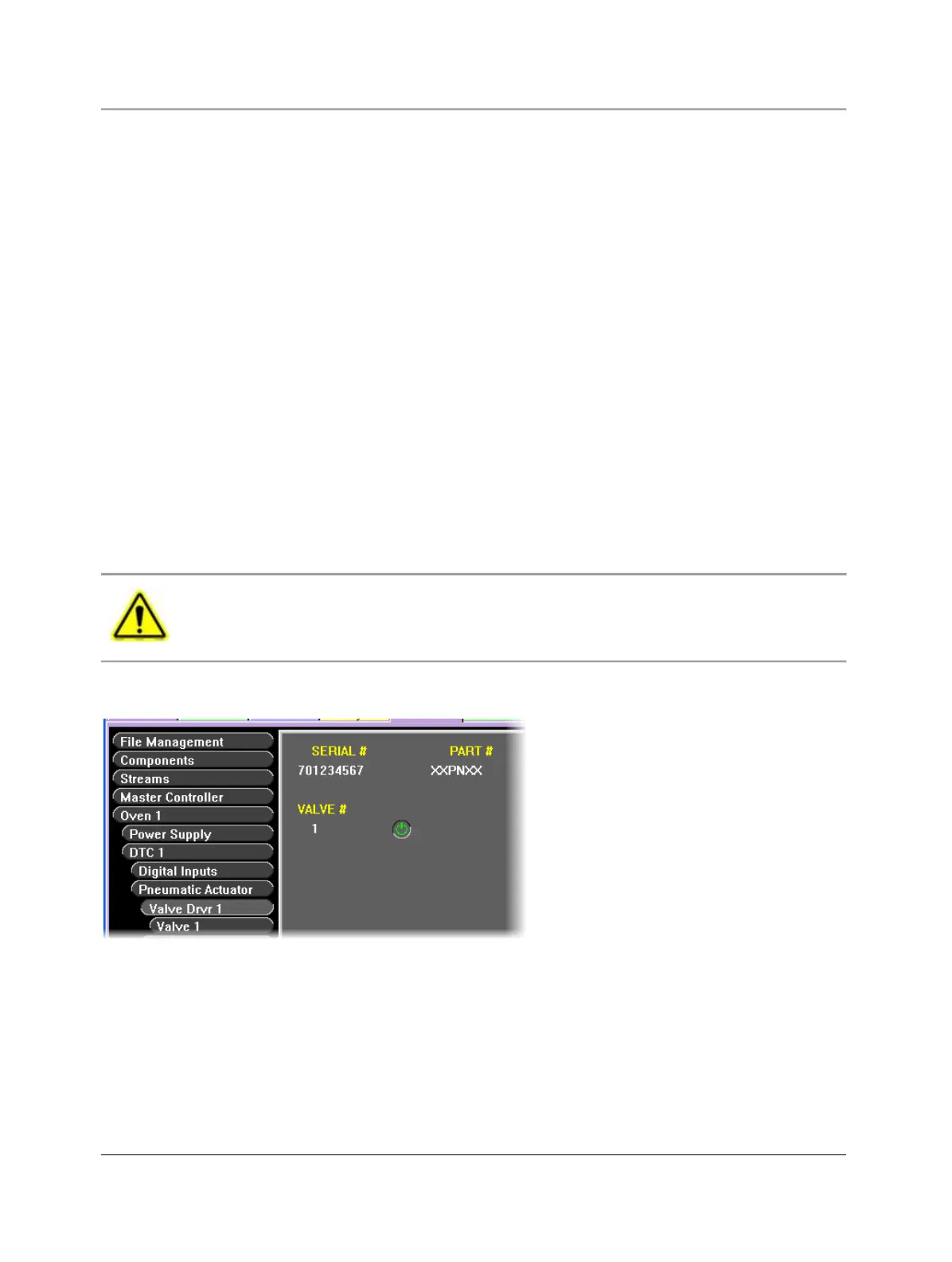
Analytical valves are controlled using the valve button under the Setup Tab (see Figure 3.1). Refer to the Data Package for flow
rates and pressures applicable to your analyzer.
Fig. 3.1. Analytical Valve Control Screen
Select applicable valves from the list on the left side of the folder display. Adjust as necessary for the application.