Analog input 5; the voltage transformer for phase 2 to earth must be
connected on pins 5 and 1.
Analog input 6; the voltage transformer for phase 3 to earth must be
connected on pins 23 and 19.
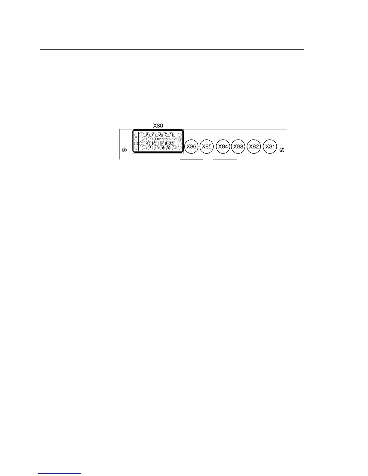
Analog input 7, for the toroidal transformer for the residual current must be
connected on pins 24 and 16 (common).
A051453
Fig. 18.1.-3 Connector for mixed analog input modu le
The picture above shows the connector for the mixed analog input module
when both sensors and conventional instrument transformers are used. To
find out which connector is used for what, identify the module code from the
identification label stick on the unit and see Table 18.1.-1.
18.2. Binary inputs and outputs
Binary input and output modules use the following connectors:
X20 (inputs), X21 (outputs) for the first module.
X30 (inputs), X31 (outputs) for the second module.
X40 (inputs), X41 (outputs) for the third module, available with the wide
housing only.
REF542plus can be equipped with two different types of binary inputs and
outputs modules: static or with electromechanical relays.
18.2.1. Static
In the static module, digital inputs are implemented with optocouplers and
digital outputs are implemented with power transistors. Two different module
types are available, with control coil continuity and without.
Each module features: 14 digital inputs, 3 power outputs, 4 normal outputs, 2
signal outputs, 1 watchdog output and optionally 2 coil supervision circuits.
For more information, refer to the REF542plus Technical Catalogue.
72
REF542plus
Multifunction Protection and Switchgear Control
Unit
Operator's manual
1MRS755869