75
18.3. Other connections
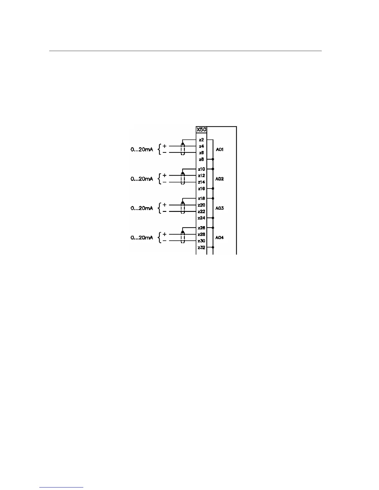
18.3.1. Analog outputs 0/4-20 mA
The 4 analog outputs, when present, are available at connector X50
accordingly to the following …x-ref…diagram. The not used pins, including
the shielding of the cable are connected to ground.
A051457
Fig. 18.3.1.-1 0/4-20 mA analog outputs
18.3.2. Analog inputs 4-20 mA
When present, the 4-20 mA analog input module uses connector X50.
Sensor’s connections are shown in the picture below…x-ref… X51 and X52
are service interfaces of no use for the user. The output contact BO1 is for the
future use.
1MRS755869
Multifunction Protection and Switchgear Control
Unit
Operator's manual
REF542plus