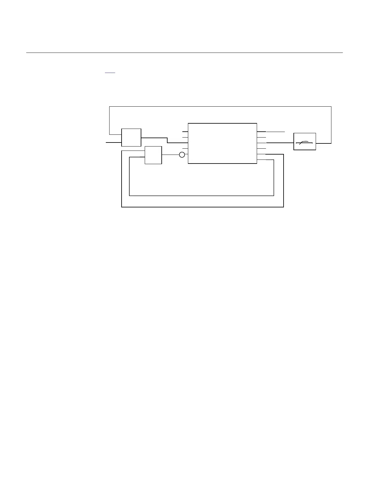
To apply the VRPVOC(51V) function, the configuration is done according to figure
203. As seen in the figure, the pickup of the overcurrent stage will enable the
undervoltage stage. Once enabled, the undervoltage stage will start a timer, which
causes function tripping, if the voltage does not recover above the set value. To ensure
a proper reset, the function is blocked two seconds after the trip signal is issued.
Trip output
OR
OR
t
ANSI12000183-1-en.vsd
VRPVOC (51V)
I3P*
I3P*
V3P*
V3P*
BLOCK
BLOCK
BLKOC
BLKOC
BLKUV
BLKUV
TRIP
TRIP
TROC
TROC
27 Trip
27 Trip
PICKUP
PICKUP
PU_OC
PU_OC
27 PU
27 PU
ANSI12000183 V1 EN-US
Figure 203: Undervoltage seal-in of current pickup
9.14.3 Setting guidelines
GUID-2AE85EC4-669E-47C0-ADD4-3DBA83581096 v2
9.14.3.1 Explanation of the setting parameters
GUID-9B777E6D-602B-4214-9170-A44ED2D725BF v3
Operation: Set to On in order to activate the function; set to Off to switch off the
complete function.
Pickup_Curr: Operation phase current level given in % of IBase.
Characterist: Selection of time characteristic: Definite time delay and different types
of inverse time characteristics are available; see Technical Manual for details.
tDef_OC: Definite time delay. It is used if definite time characteristic is chosen; it shall
be set to 0 s if the inverse time characteristic is chosen and no additional delay shall be
added. Note that the value set is the time between activation of the start and the trip
outputs.
k: Time multiplier for inverse time delay.
Section 9 1MRK 502 071-UUS A
Current protection
428 Generator protection REG670 2.2 ANSI and Injection equipment REX060, REX061, REX062
Application manual

 Loading...


