8.13.2.1 System grounding
GUID-FC9BF10E-8CA1-4B23-887D-2EAB6A2A0A6E v1
The type of system grounding plays an important role when designing the protection
system. Some hints with respect to distance protection are highlighted below.
Solidly grounded
networks
GUID-6870F6A8-EB28-47CF-AF26-7CE758BF934E v1
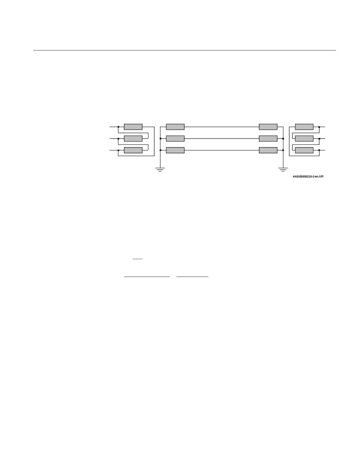
In solidly grounded systems, the transformer neutrals are connected directly to ground
without any impedance between the transformer neutral and ground.
ANSI05000215 V2 EN-US
Figure 188: Solidly grounded network
The ground-fault current is as high or even higher than the short-circuit current. The
series impedances determine the magnitude of the fault current. The shunt admittance
has very limited influence on the ground-fault current. The shunt admittance may,
however, have some marginal influence on the ground-fault current in networks with
long transmission lines.
The ground-fault current at single phase-to-ground in phase A can be calculated as
equation 304:
A A
0
1 2 0 f 1 N f
3 V
3I
Z Z Z 3Z Z Z Z
V×
= =
+ + + + +
EQUATION1710 V2 EN-US (Equation 304)
Where:
VA is the phase-to-ground voltage (kV) in the faulty phase before fault.
Z
1
is the positive sequence impedance (Ω/phase).
Z
2
is the negative sequence impedance (Ω/phase).
Z
0
is the zero sequence impedance (Ω/phase).
Z
f
is the fault impedance (Ω), often resistive.
Z
N
is the ground-return impedance defined as (Z
0
-Z
1
)/3.
1MRK 504 163-UUS A Section 8
Impedance protection
Transformer protection RET670 2.2 ANSI 397
Application manual