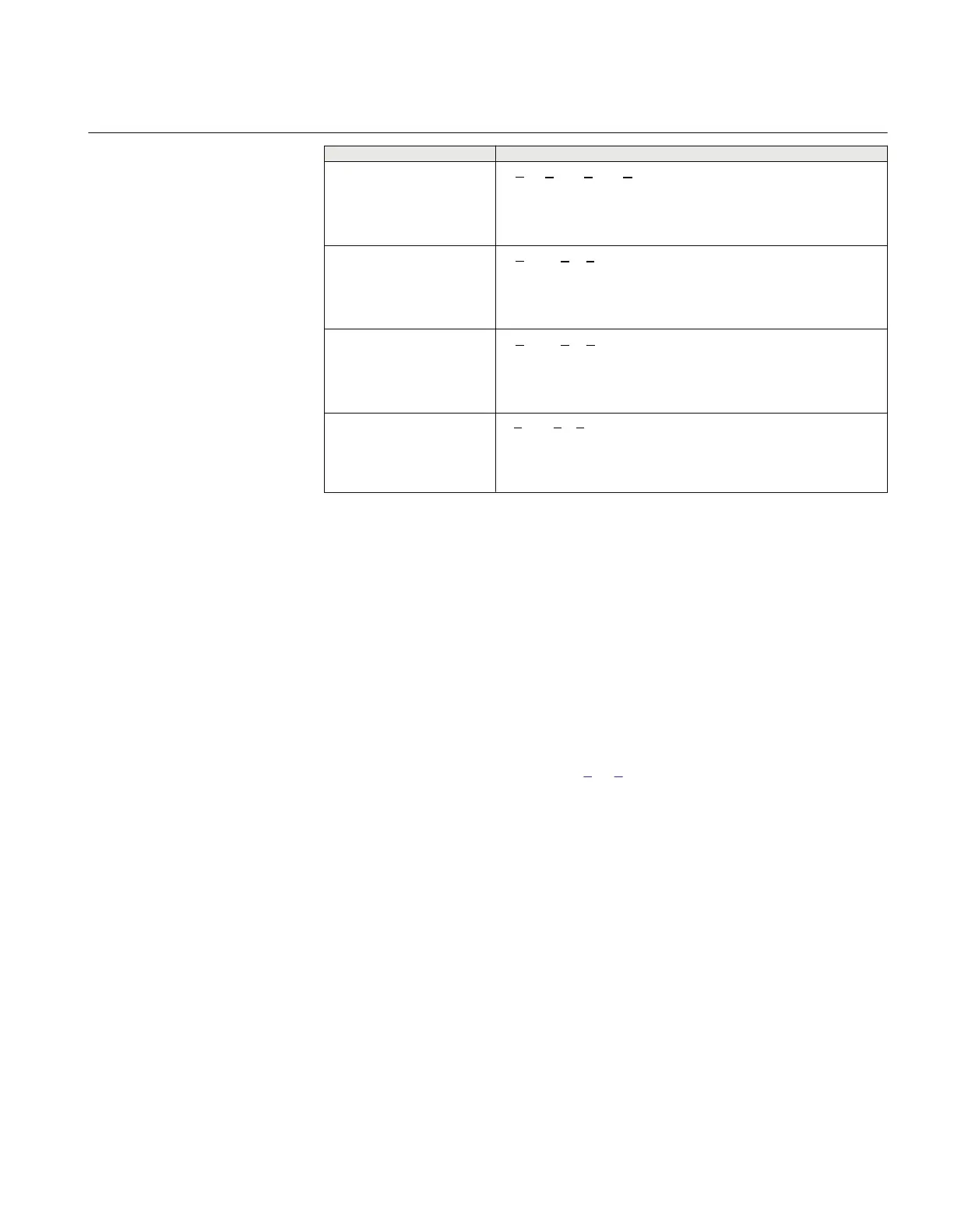
Set value:
Mode
Formula used for complex power calculation
CA
EQUATION2060-ANSI V1 EN (Equation 9)
A
EQUATION2061-ANSI V1 EN (Equation 10)
B
EQUATION2062-ANSI V1 EN (Equation 11)
C
EQUATION2063-ANSI V1 EN (Equation 12)
2. Adjust the injected current and voltage to the set values in % of IBase and VBase
(converted to secondary current and voltage). The angle between the injected current
and voltage shall be set equal to the set direction Angle1, angle for stage 1 (equal to
0° for low forward power protection and equal to 180° for reverse power protection).
Check that the monitored active power is equal to 100% of rated power and that the
reactive power is equal to 0% of rated power.
3. Change the angle between the injected current and voltage to Angle1 + 90°. Check
that the monitored active power is equal to 0% of rated power and that the reactive
power is equal to 100% of rated power.
4. Change the angle between the injected current and voltage back to 0°. Decrease the
current slowly until the PICKUP1 signal, pickup of stage 1, is activated.
5. Increase the current to 100% of IBase.
6. Switch the current off and measure the time for activation of TRIP1, trip of stage 1.
7. If a second stage is used, repeat steps
2 to 6 for the second stage.
6.3.14.2 Completing the test
Continue to test another function or end the testing by setting the parameter TestMode to
Disabled under Main menu/Tests/IED test mode/TESTMODE:1. If another function is
tested, then set the parameter Blocked to No under Main menu/Tests/Function test
modes/Current/GUPPDUP(37,P<)/GUPPDUP:1 for the function, or for each
individual function in a chain, to be tested next. Remember to set the parameter Blocked to
Yes, for each individual function that has been tested.
1MRK 505 293-UUS A Section 6
Testing functionality
73
Commissioning manual