Detailed network studies can determine the operating conditions under which the
highest possible fault current is expected on the line . In most cases, this current
appears during three-phase fault conditions. But also examine single-phase-to-earth
and two-phase-to-earth conditions.
Also, study transients that could cause a high increase of the line current for short
times. A typical example is a transmission line with a power transformer at the remote
end, which can cause high inrush current when connected to the network and can thus
also cause the operation of the built-in, instantaneous, overcurrent protection.
Common base IED values for primary current (IBase), primary voltage (setting
UBase) and primary power (SBase) are set in a Global base values for settings function
GBASVAL. Setting GlobalBaseSel is used to select a GBASVAL function for
reference of base values.
IP>>: Set operate current in % of IBase.
6.2.3.1 Meshed network without parallel line
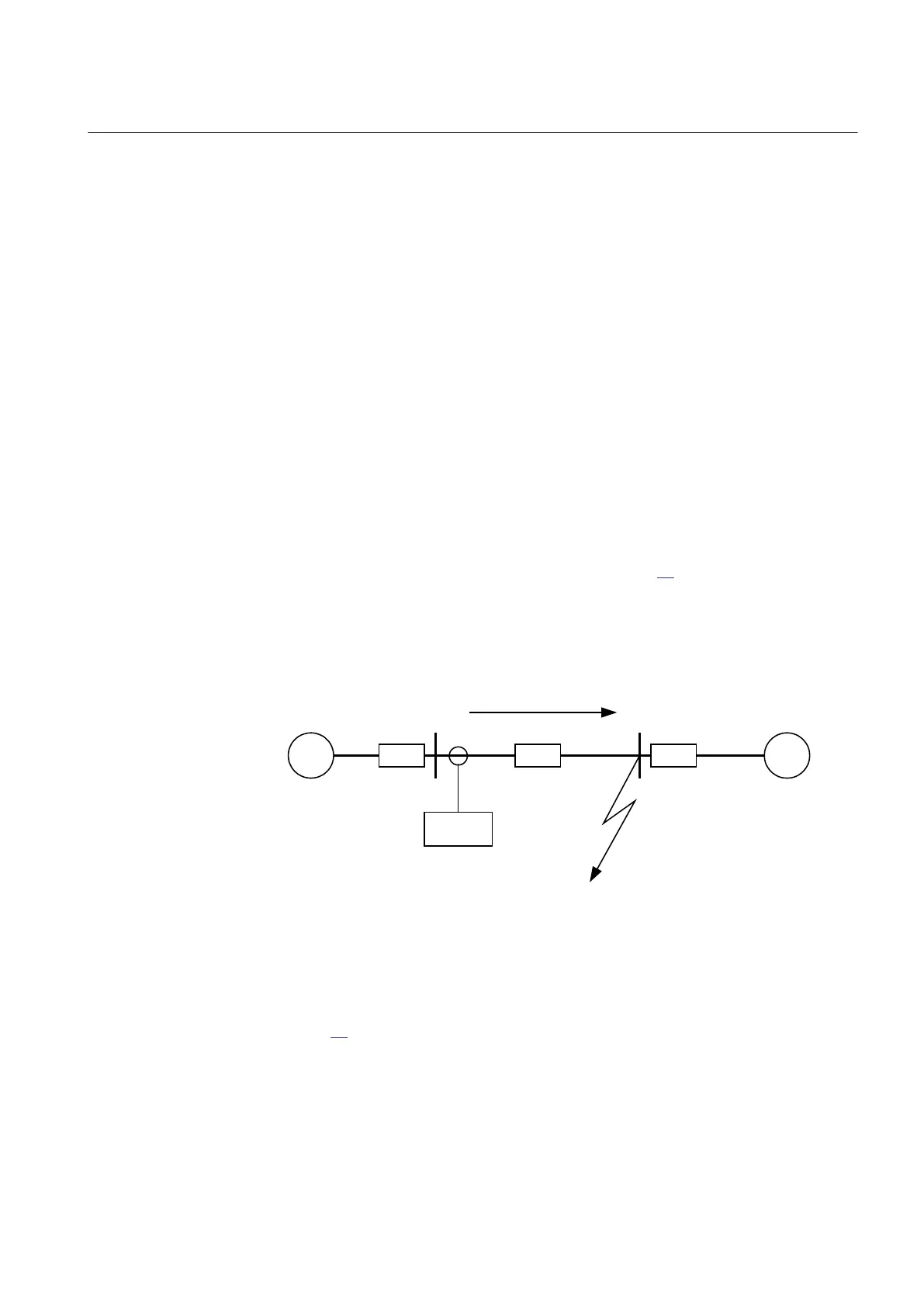
The following fault calculations have to be done for three-phase, single-phase-to earth
and two-phase-to-earth faults. With reference to figure
42, apply a fault in B and then
calculate the current through fault phase current I
fB
. The calculation should be done
using the minimum source impedance values for Z
A
and the maximum source
impedance values for ZB in order to get the maximum through fault current from A to
B.
~
~
Z
A
Z
B
Z
L
A B
IED
I
fB
Fault
IEC10000277-1-en.vsd
IEC10000277 V1 EN
Figure 42: Through fault current from A to B: I
fB
Then a fault in A has to be applied and the through fault current I
fA
has to be calculated,
figure 43. In order to get the maximum through fault current, the minimum value for
Z
B
and the maximum value for Z
A
have to be considered.
1MRK 505 291-UEN A Section 6
Current protection
91
Application manual