3
3
1
REQ650 (A01)
Z
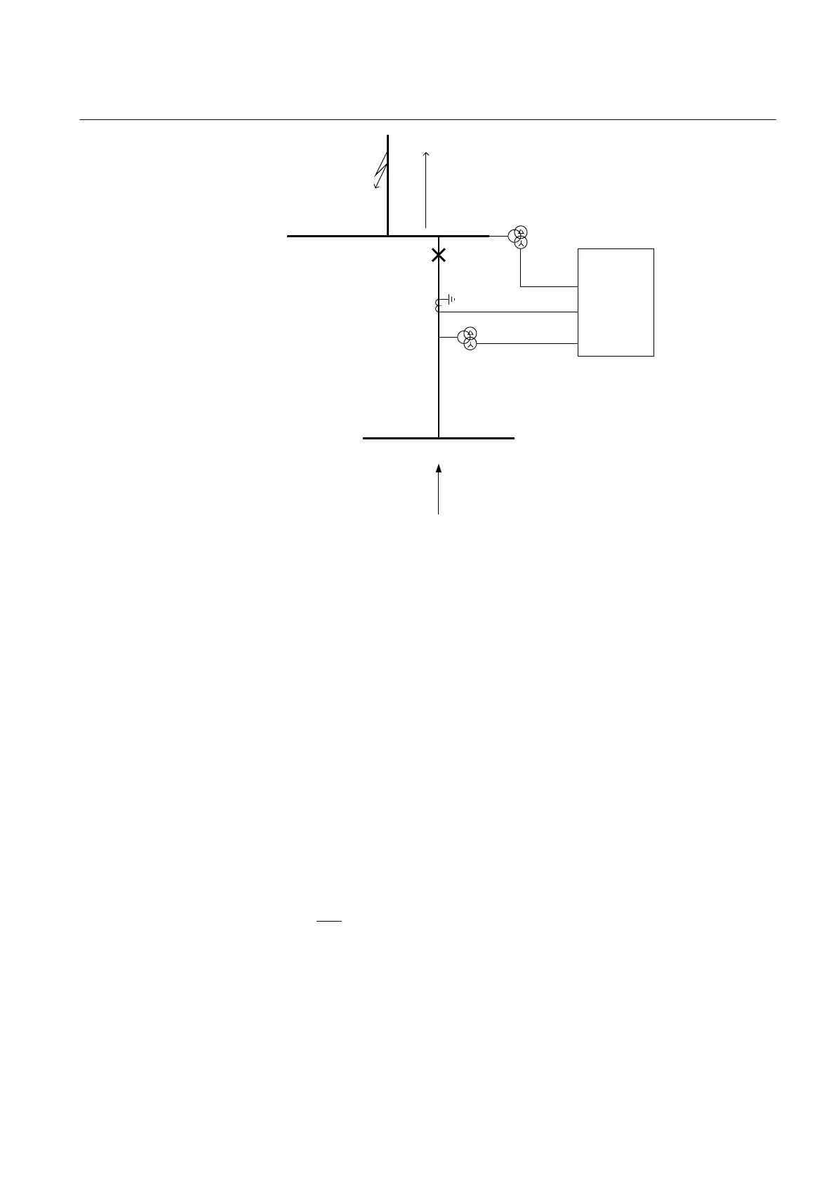
SC
: Low
Three phase short circuit
Line protection zone 1 reach
IEC10000150-1-en.vsd
IEC10000150 V1 EN
Figure 16: Fault for step 2 setting
Recommended current setting is therefore 2000 A.
1. Set DirMode2 to Reverse.
2. Set Characterist1 is set to IEC Def. Time.
For the time delay characteristic, definite time is used in this network.
3. Set I2> to 200% of IBase (2000 A primary current).
4. Set t2 to 0.4 s.
3.1.5.4 Calculating settings for step 3
The phase overcurrent protection shall never trip for load current in extreme high load
situations. The maximum load current through the coupler bay is 750 A (the same as
the CT-rated current), corresponding to about 190 MVA. The resetting ratio is 0.95.
The minimum setting can be calculated:
1
3 750 790
0.95
I A> ³ × × =
EQUATION2344 V1 EN
1. Set DirMode3 to Non-directional.
2. Set Characterist1 is set to IEC Def. Time.
1MRK 505 291-UEN A Section 3
REQ650 setting examples
51
Application manual