L1
IL1
IL2
IL3
L2 L3
Protected Object
CT 800/1
Star Connected
IL1
IL2
IL3
IED
IEC11000026-4-en.vsdx
4
1
2
3
SMAI2
BLOCK
REVROT
^GRP2L1
^GRP2L2
^GRP2L3
^GRP2N
AI3P
AI1
AI2
AI3
AI4
AIN
5
IN
IEC11000026 V4 EN
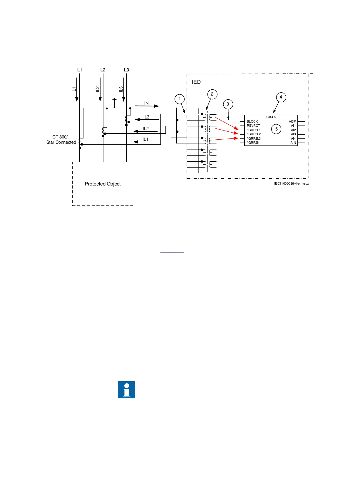
Figure 27: Star connected three-phase CT set with its star point away from the protected object
In the example in figure 27 case everything is done in a similar way as in the above
described example (figure 26). The only difference is the setting of the parameter
CTStarPoint of the used current inputs on the TRM (item 2 in the figure):
• CTprim=600A
• CTsec=5A
• CTStarPoint=FromObject
Inside the IED only the ratio of the first two parameters is used. The third parameter
as set in this example will negate the measured currents in order to ensure that the
currents are measured towards the protected object within the IED.
4.2.3.5 Example how to connect single-phase CT to the IED
Figure
28 gives an example how to connect the single-phase CT to the IED. It gives
an overview of the required actions by the user in order to make this measurement
available to the built-in protection and control functions within the IED as well.
For correct terminal designations, see the connection diagrams valid
for the delivered IED.
1MRK 505 291-UEN A Section 4
Analog inputs
69
Application manual