IEC09000024-1-en.vsd
~ ~
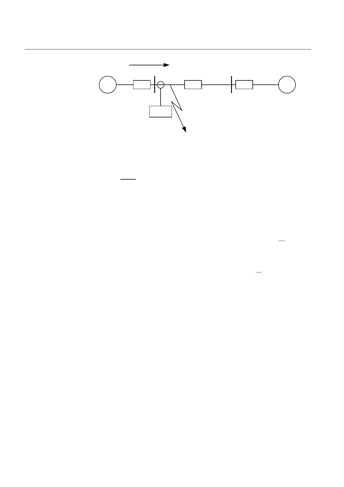
Z
A
Z
B
Z
L
A B
IED
I
F
Fault
IEC09000024 V1 EN
Figure 40: Fault current: I
F
EQUATION1147 V3 EN (Equation 5)
6.1.3.2 Meshed network with parallel line
In case of parallel lines, the influence of the induced current from the parallel line to
the protected line has to be considered. One example is given in figure 41 where the
two lines are connected to the same busbars. In this case the influence of the induced
fault current from the faulty line (line 1) to the healthy line (line 2) is considered
together with the two through fault currents I
fA
and I
fB
mentioned previously. The
maximal influence from the parallel line for the IED in figure 41 will be with a fault
at the C point with the C breaker open.
A fault in C has to be applied, and then the maximum current seen from the IED (I
M
)
on the healthy line (this applies for single-phase-to-earth and two-phase-to-earth
faults) is calculated.
Section 6 1MRK 505 291-UEN A
Current protection
88
Application manual