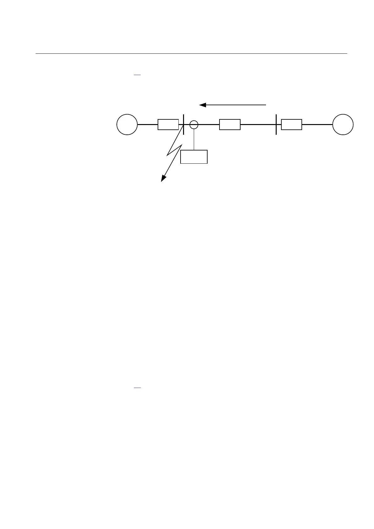
Then a fault in A has to be applied and the through fault current I
fA
has to be calculated,
figure 39. In order to get the maximum through fault current, the minimum value for
Z
B
and the maximum value for Z
A
have to be considered.
IEC09000023-1-en.vsd
~ ~
Z
A
Z
B
Z
L
A B
IED
I
fA
Fault
IEC09000023 V1 EN
Figure 39: Through fault current from B to A: I
fA
The IED must not trip for any of the two through-fault currents. Hence the minimum
theoretical current setting (Imin) will be:
EQUATION78 V1 EN (Equation 3)
A safety margin of 5% for the maximum protection static inaccuracy and a safety
margin of 5% for the maximum possible transient overreach have to be introduced. An
additional 20% is suggested due to the inaccuracy of the instrument transformers
under transient conditions and inaccuracy in the system data.
The minimum primary setting (Is) for the instantaneous phase overcurrent protection
3-phase output is then:
EQUATION79 V3 EN (Equation 4)
The protection function can be used for the specific application only if this setting
value is equal to or less than the maximum fault current that the IED has to clear, I
F
in
figure
40.
1MRK 505 291-UEN A Section 6
Current protection
87
Application manual