12 Specifications FSM4000
D184B122U02 S4 63
12 Specifications FSM4000
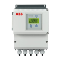
12.1 General Description
The Converter Model S4 converts the flowrate proportional flow signals from an electromagnetic flowmeter
primary into the conventional output signals. These measurement values are shown on a full-graphic 4 line
lighted display. In addition, the measurement values are also transmitted to a scaled pulse output, current
output and using HART-Protocol communication. In the variant PROFIBUS PA, the measurement values are
transmitted over the PROFIBUS and are also available at a contact output. The flow range end value of the
converter can be set within the range from 0.5 m/s to 10 m/s. This metering system is especially suited for
applications with fast changing or two phase flows.
The incorporation of a digital signal processing assures a high system reliability especially in interference
environments, noise intensive fluids and for fast changing flows. Furthermore, standard are a pulsation free
current output, pulse output (active or passive), fast response times, automatic empty pipe detection and
much more. Therefore this EMF is especially suited for demanding applications and two phase flows.
12.2 Converter Model S4
Housing material Fluidized bed powder coated Aluminum die casting
Coating Epoxy powder
primer None
surface preparation Washed in a high alkaline bath; Alodine process applied
as a corrosion layer to improve adhesion of coating
Coating thickness 80 µm
Color RAL 9002 (light gray)
RAL 7012 (basalt gray)
Protection Class per EN 60529 IP 67, NEMA 4X,
Ambient temperature -20°C to + 60°C
Storage temperature -20°C to + 80°C
Shock and vibration resistance per IEC 60068-2-3
Cable entries M20x1.5; NPT ½" option; PF ½" option
Supply power U
High
AC 85–253 V, 47/63 Hz
U
Low
AC 20.4-26.4 V, 47/63 Hz
DC 20.4-31.2 V (ripple < 5%)
Power S ≤ 45 VA (flowmeter primary including converter)
Galvanic isolation Current output, pulse output, contact input and contact output are
galvanically isolated from the signal input and each other
Flow range setting 0 to 0.5 and 0 to 10 m/s
Response time 1 τ = 70 ms (0–63 % flowrate change) Operating Mode Fast
1 τ = 200 ms (0–63 % flowrate change) Operating Mode Standard,
Piston Pump
Current output 0/4–20 mA; 0/2–10 mA selectable, galvanically isolated,
R
L
< 560 Ω, (for HART min. 250 Ω)
Pulse output Active/passive switchable, galvanically isolated,
active Voltage pulse 24V rectangular, R
L
> 150 Ω,
Pulse width ≤ 50 ms, count frequency ≤ 3 Hz,
R
L
> 500 Ω, pulse width ≥ 0.1 ms count frequency 5 kHz
passive Apply external voltage, optocoupler specifications:
„closed“ Voltage 16 V ≤ U
CEH
≤ 30 V; current 2 mA ≤ I
CEH
≤ 220 mA
„open“ Voltage 0 V ≤ U
CEL
≤ 2 V; current 0 mA ≤ I
CEL
≤ 2 mA
Pulse factor Settable within dynamic limits in pulses/unit
Pulse width Settable within dynamic limits from 0.1 to 2000 ms

 Loading...
