SwirlMaster FSS430, FSS450 VortexMaster FSV430, FSV450 | CI/FSS/FSV430/450-EN Rev. D 19
5.2 Installing the sensor
Observe the following points during installation:
— The flow direction must correspond to the marking, if
present
— The maximum torque for all flanged connections must be
observed
— The devices must be installed without mechanical tension
(torsion, bending)
— Wafer type devices with plane parallel counterflanges may
only be installed with suitable gaskets
— Only gaskets made from a material that is compatible with
the measuring medium and measuring medium
temperature may be used
— The piping may not exert any inadmissible forces or
torques on the device
— Do not remove the sealing plugs in the cable glands until
you are ready to install the electrical leads
— Make sure the gaskets for the housing cover are seated
correctly Carefully seal the cover. Tighten the cover fittings
— Do not expose the transmitter to direct sunlight and
provide for appropriate sun protection where necessary
— When selecting the installation site, make sure that
moisture cannot penetrate the terminal or transmitter
compartment
The device can be installed at any location in a pipeline under
consideration of the installation conditions.
1. Position the meter tube coplanar and centered between
the piping.
2. Install gaskets between the sealing surfaces.
NOTE
For achieve the best results, ensure the gaskets fit
concentrically with the meter tube
To ensure that the flow profile is not distorted, the gaskets
must not protrude into the piping.
3. Use the appropriate screws for the holes.
4. Slightly grease the threaded nuts.
5. Tighten the nuts in a crosswise manner as shown in the
figure. First tighten the nuts to approx. 50 % of the
maximum torque, then to 80 %, and finally a third time to
the maximum torque.
NOTE
Torques for screws depend on temperature, pressure, screw
and gasket materials. The relevant applicable regulations
must be taken into consideration.
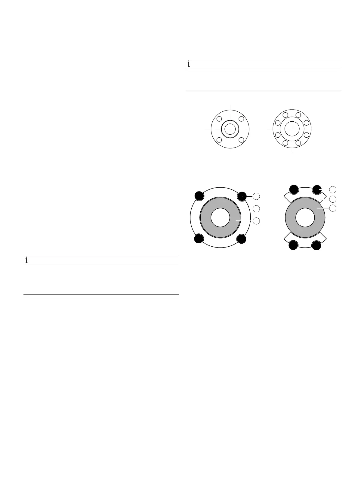
Fig. 14: Tightening sequence for the flange screws
5.2.1 Centering the wafer type design
Fig. 15: Centering the wafer type design with the ring or segment
1 Bolt 2 Centering ring 3 Meter tube (wafer type)
4 Centering segment
Wafer type devices (FV400 only) are centered via the outside
diameter of the flowmeter sensor body with the corresponding
bolts.
Depending on the nominal pressure rating, sleeves for the
bolts, a centering ring (up to DN 80 [3"]) or segments can be
ordered as additional accessories.
G11726
1
2
7
8
5
3
4
6
1
2
3
4
G11763
1
2
3
1
4
3

 Loading...


