24 CI/FSS/FSV430/450-EN Rev. D | SwirlMaster FSS430, FSS450 VortexMaster FSV430, FSV450
5.4.1 Electrical data for inputs and outputs
Power supply, current output / HART output
Power supply, current output / HART output
Supply voltage 12 ... 42 V DC
Residual ripple Maximum 5 % or ±1.5 Vpp
Power consumption < 1 W
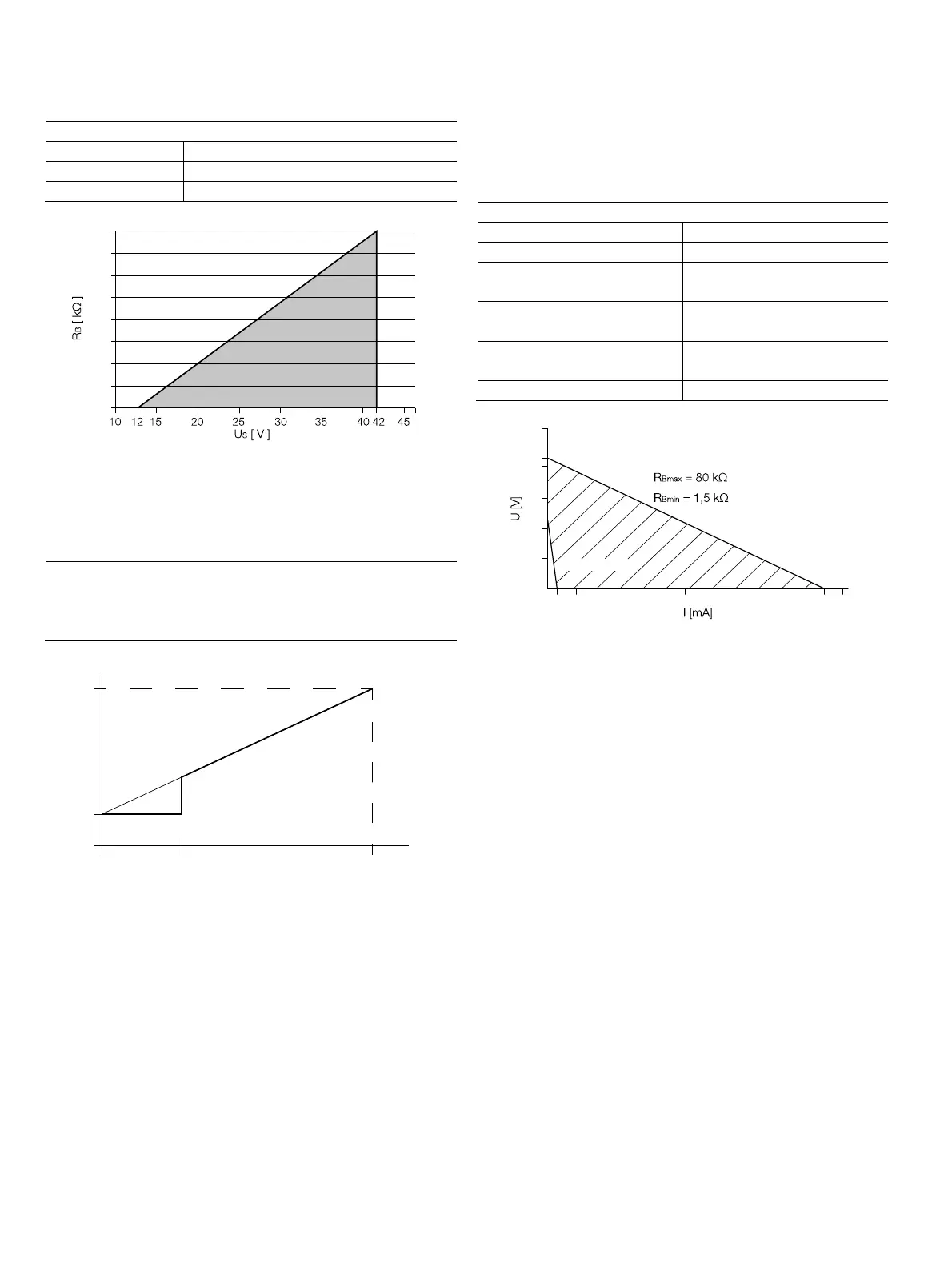
Fig. 22: Load diagram of the current output; load vs. supply voltage
In HART communication, the smallest load is 250 Ω. The load
R
B
is calculated as a function of the available supply voltage
U
S
and the selected signal current I
B
as follows:
R
B
= U
S
/ I
B
R
B
Load resistance
U
S
Supply voltage
I
B
SignalStrom
Fig. 23: Behavior of the current output
1 Low flow cut-off
The measured value at the current output behaves as shown
in the figure.
The current curve proceeds above the low flow as a straight
line, which in the Q = 0 operating mode has the value 4 mA
and in the Q = Q
max
operating mode has the
value 20 mA.
Due to the low flow cut-off, the flow is set to below x % Qmax
or the low flow is set to 0, meaning the current is 4 mA.
Digital output
The devices can be ordered with an optional digital output.
This output can be configured by software as:
— Frequency output (up to 10.5 kHz)
— Pulse output (up to 2 kHz)
— Logic output (on / off, e.g. to display an alarm signal)
Digital output
Operating voltage 16 ... 30 V DC
Output current Maximum 20 mA
Output "closed" 0 V ≤ U
low
≤ 2 V
2 mA ≤I
low
≤ 20 mA
Output "open" 16 V ≤ U
high
≤ 30 V
0 mA ≤I
hi
h
≤ 0.2 mA
Pulse output f
max
: 10 kHz
Pulse width: 0.05 ... 2000 ms
Frequency output f
max
: 10.5 kHz
Fig. 24: Range of the external supply voltage and current
The external resistance R
B
is in the range of
1.5 kΩ ≤ R
B
≤ 80 kΩ, as shown in Fig. 24.
G11769
1,6
1,4
1,2
1,0
0,8
0,6
0,4
0,2
0
G11770
20 mA
4mA
Q
max
1
G11771
0,2 2 10 20 22
7
14
16
21
28
30
35
 Loading...


