22 CI/FSS/FSV430/450-EN Rev. D | SwirlMaster FSS430, FSS450 VortexMaster FSV430, FSV450
5.3.2 Earthing
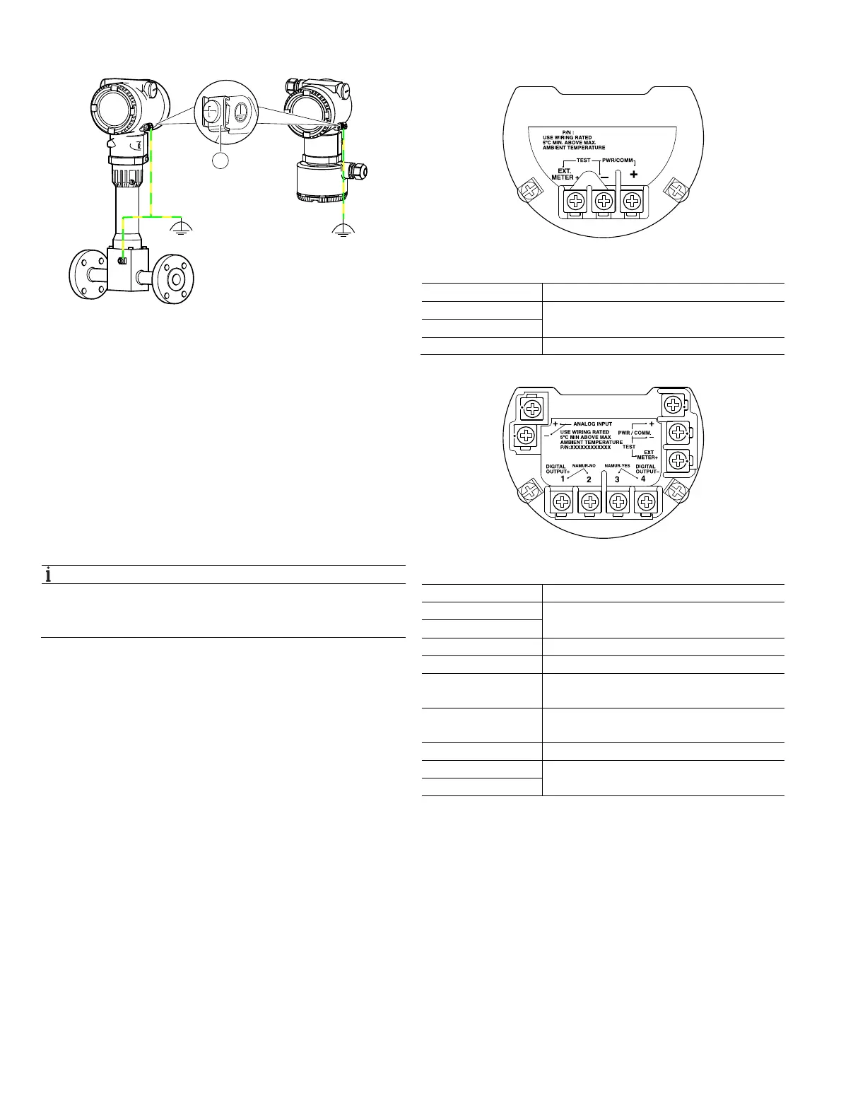
Fig. 18: Earthing terminals
1 Integral mount design and sensor in remote design
2 Transmitter in remote mount design
3 Earthing terminal
For the earthing (PE) of the transmitter or the connection of a
protective earth, a connection is available both on the exterior
of the housing and in the connection space. Both connections
must be galvanically connected to one another.
These connection points can be used if grounding or the
connection of a protective conductor is prescribed by national
regulations for the selected type of supply or the type of
protection used.
NOTE
In order to avoid external influences on the measurement, it
is imperative to ensure that the transmitter and the separate
flowmeter sensor are properly earthed.
1. Loosen the screw terminal on the transmitter housing or
on the housing of the VortexMaster / SwirlMaster.
2. Insert the forked cable lug for functional earthing between
the two metal tabs and into the loosened terminal.
3. Tighten the screw terminal.
5.3.3 Electrical connection
Fig. 19: Terminals without digital output
Terminal Function / comment
PWR/COMM + Power supply, current output / HART output
PWR/COMM -
EXT. METER Not assigned
Fig. 20: Terminals with digital output and analog input
Terminal Function / comment
PWR/COMM + Power supply, current output / HART output
PWR/COMM -
EXT. METER + Current output 4 ... 20 mA for external display
DIGITAL OUTPUT 1+ Digital output, positive pole
DIGITAL OUTPUT 2 Bridge after terminal 1+, NAMUR output
deactivated
DIGITAL OUTPUT 3 Bridge after terminal 4-, NAMUR output
activated
DIGITAL OUTPUT 4- Digital output, negative pole
ANALOG INPUT + Analog input 4 ... 20 mA for remote transmitter,
e.g. for temperature, pressure, etc.
ANALOG INPUT -
Change from two to one column
G11774
12
3
G11766
G11767
 Loading...


