26 CI/FSS/FSV430/450-EN Rev. D | SwirlMaster FSS430, FSS450 VortexMaster FSV430, FSV450
5.4.2 Connection to remote mount design
The remote mount designs are based on the integral mount
designs of the devices with all options.
The transmitter is installed separately from the sensor, if this is
positioned in a location which is difficult to access.
This design can also be advantageous if the measuring point
is located in extreme ambient conditions.
The distance between the sensor and the transmitter must not
exceed 30 m (99 ft).
A special cable connects the sensor to the transmitter. The
cable is permanently connected to the transmitter.
Once installation is complete, cut the connecting cable to
length as far as the flowmeter sensor.
The transmission signal between the sensor and the
transmitter is not amplified, so the connections need to be
routed carefully. Lay the wires in the terminal box so that they
are not affected by vibration.
NOTE
— The signal cable carries a voltage signal of only a few
millivolts. Therefore, it must be routed over the shortest
possible distance. The maximum permissible signal
cable length is 30 m (99 ft).
— Route all leads in such a way that they are shielded, and
connect to the operational earth potential. For this
purpose, the cable shield must be connected
underneath the cable clamp.
— Avoid installing the signal cable in the vicinity of electrical
equipment or switching elements that can create stray
fields, switching pulses and induction. If this is not
possible, run the signal cable through a metal pipe and
connect this to the operational earth potential.
— Make sure during installation that the cable is fitted with
a drip loop (water trap)
— For vertical installation of the meter tube, align the cable
glands pointing downward
5.4.3 Cutting the signal cable to length and terminating it
Fig. 27: Signal cable dimensions in mm (inch)
The signal cable is available in four standard lengths: 5 m
(16.4 ft), 10 m (32.8 ft), 20 m (65.6 ft) and 30 m (98.4 ft).
The cable ends are already prepared for installation.
However, the cables can also be cut to any length.
For proper installation, the cable ends must be prepared as
shown in Fig. 27.
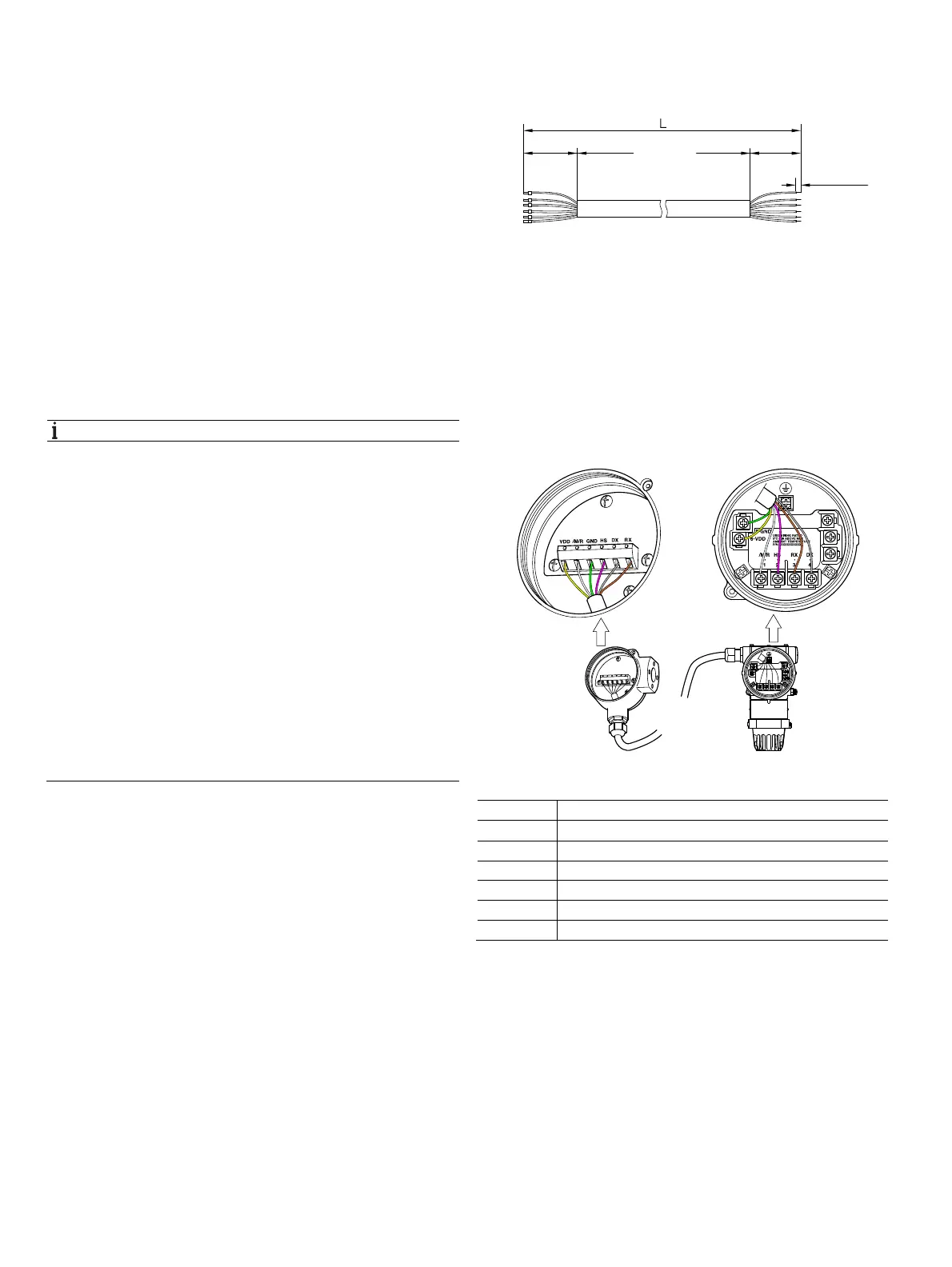
5.4.4 Connecting the signal cable
Fig. 28
Terminal Color
VDD Yellow
/M/R White
GND Green
HS Pink
DX Gray
RX Brown
G11775
12 1±
(0.5 0.04)±
50 3±
(2 0.12)±
50 3±
(2 0.12)±
G11776

 Loading...


