40 CI/FSS/FSV430/450-EN Rev. D | SwirlMaster FSS430, FSS450 VortexMaster FSV430, FSV450
7.3.1 Process display
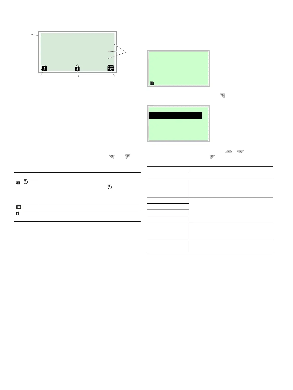
Fig. 33: Process display (example)
1 Measuring point tagging 2 Current process values
3 "Button function" symbol
4 "Parameterization protected" symbol
The process display appears on the LCD display when the
device is switched on. It shows information about the device
and current process values.
The way in which the current process values are shown can
be adjusted on the configuration level.
The symbols at the bottom of the process display are used to
indicate the functions of the operating buttons and , in
addition to other information.
Symbol Description
/
Call up information level.
When Autoscroll mode is activated, the symbol
appears here and the operator pages are automatically
displayed one after the other.
Call up configuration level.
The device is protected against changes to
parameterization.
7.3.2 Switching to the information level (operator menu)
On the information level, the operator menu can be used to
display diagnostic information and choose which operator
pages to display.
Process display
1. Open the Operator Menu using .
Operator Menu
Diagnostics
Operator Page 1
Operator Page 2
Back Select
2. Select the desired submenu using / .
3. Confirm the selection with .
Menu Description
… / Operator Menu
Diagnostics Selection of sub-menu "„Diagnostics"; see
also chapter „Error messages on the LCD
display“ on page 41.
Operator Page 1 Selection of operator page to be displayed.
Operator Page 2
Operator Page 3
Operator Page 4
Autoscroll When Autoscroll is activated, automatic
switching of the operator pages is initiated on
the process screen.
Signal view Selection of submenu "Signal view" (only for
service purposes).
G11783
Pump 1
1
43
2
3
QNP 0.00 m3/h
QD 69.516910 %
QD 69.516910 %
 Loading...


