Operating Instructions SYN 5201/SYN 5202
Document No Art Part Language Revision page
abb
ABB Switzerland Ltd
3BHS109762 E01
en D 26
Template: CHIND Techn doc stand, A4 P de, R1.DOT; Filename: 3BHS109762E01 D.doc; Print: 12/6/2011 5:48:00 PM; Save: 12/1/2011 2:37:00 PM; CHIND No. 3BHS109763 ZAB D14 Rev. -; I-Q
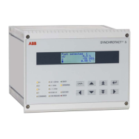
3.2 Front panel
On the front panel of the SYN 5201 or SYN 5202 there is a block of status displays, as
well as eight keys and the liquid crystal display (LCD) of the built-in service controls.
Status displays (LED)
The status display consists of 3 rows of LEDs which are sub-divided as follows:
Group Designation Function
Left-hand row:
commands
U+, U-, f+, f-
COMMAND
(colour: yellow)
Indicate outgoing commands, i.e., the output of the
Higher and Lower commands for voltage and
frequency and the paralleling command
Centre row:
fulfilled paralleling
conditions
U Umax
s smax
max
U1/U2 = 0
CHK RELEASE
(colour: yellow)
Indicate if
U,
and s are within the tolerance band
or at least one measuring voltage is lacking.
Indicates paralleling release (only in synchrocheck
mode)
Right-hand row:
operating status
READY
(colour: green)
Indicates readiness for operation
OPERATING
(colour: yellow)
Synchronizing process is in operation
BLOCKED
(colour: yellow)
Indicates the blocked status of the device, e.g. as
when carrying out commissioning work.
ERROR
(colour: red)
Indicates that a fault message is active (the
BLOCKED LED always lights up at the same time)