Pneumatic connection
42/18-85-EN TZIDC-200, TZIDC-210, TZIDC-220 27
6 Pneumatic connection
IMPORTANT (NOTE)
The TZIDC-200, TZIDC-210, TZIDC-220 positioners must be supplied with instrument air that
is free of oil, water, and dust.
The purity and oil content should meet the requirements of Class 3 according to
DIN / ISO 8573-1.
NOTICE - Potential damage to parts!
Impurities on the pipe and positioner can damage components.
Dust, splinters, and any other particles of dirt must be blown off the pipe before it is
connected.
To connect the air pipes, G1/4 or 1/4-18 NPT tap holes are provided. We recommend that you
use a line with dimensions of 6 x 1 mm.
NOTICE - Potential damage to parts!
Pressure above 6 bar (90 psi) can damage positioners or actuators.
Provisions should be made to ensure that, in the event of an error, the pressure does not rise
above 6 bar (90 psi).
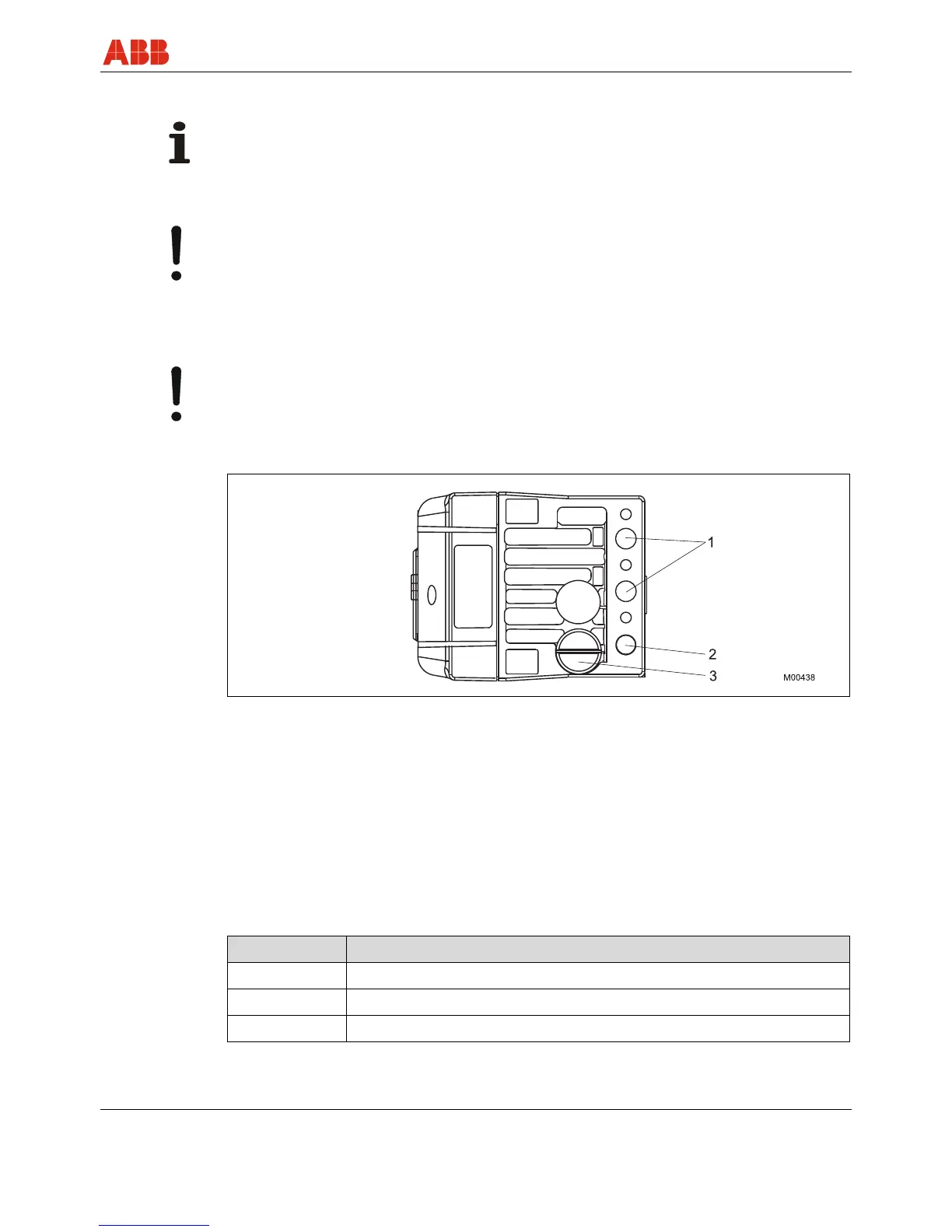
Fig. 19: Pneumatic connections
1 Pneumatic outputs
2 Supply air
3 Filter screw
All pneumatic piping connections are located on the right side of the positioner. To connect the
pneumatic pipes, G1/4 or 1/4-18 NPT tap holes are provided. The positioner is labeled
according to the tap holes available. The corresponding pipe connections must be included.
The level of supply pressure must be adjusted to the output pressure in the actuator required to
provide increased actuating force. The operating range for the positioner is between 1.4 ... 6 bar
(20 ... 90 psi).
Arrange the connections according to their marks:
Designation Pipe connection
- Air supply, pressure 1.4 ... 6 bar (20 ... 90 psi)
OUT1 Output pressure for actuator
OUT2 Output pressure for actuator (2nd connection with double-acting actuator)


 To Next Page