Electrical connections
42/18-85-EN TZIDC-200, TZIDC-210, TZIDC-220 23
5 Electrical connections
DANGER – Risk of explosion (TZIDC-200 only)
It is prohibited to use the local communication interface (LKS) in an Ex area.
Never use the local communication interface (LKS) on the main board with a positioner that is
being used in an explosion risk area.
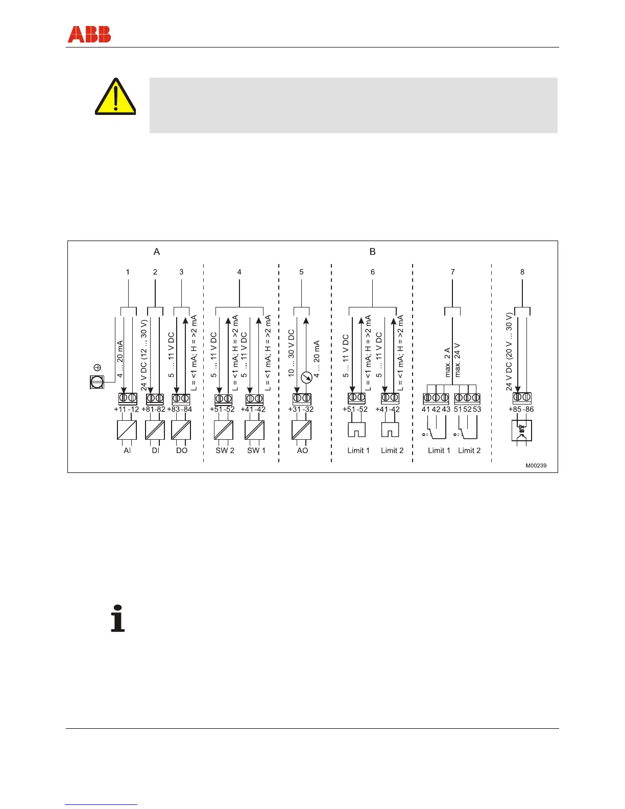
1. Strip the wire by approx. 8 mm (0.32 inch).
2. To connect the signal lines, the emergency shutdown module and the proximity switches or
microswitches, insert the wire ends from the left into the respective screw terminals and
hand-tighten the screws (access from above). To connect a plug-in module, insert the wire
ends from above in the appropriate screw terminals and hand-tighten the screws (access
from the side).
Fig. 16: Electrical connection
A Basic model
B Options
1
Analog input / Bus connector
2 Digital input
1)
3 Digital output
1)
4 Digital feedback
1)
5 Analog feedback
1)
6 Proximity switches
7 Microswitches
8 Emergency shutdown module
1) TZIDC-200 only
IMPORTANT (NOTE)
Keep cable shields as short as possible and connect on both sides.
 Loading...


