99
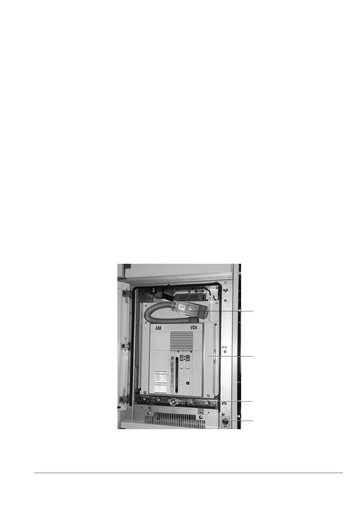
10.2
13.1
18.1
14
4. It must only be possible to open the circuit-breaker (manually) when the withdrawable part is in the
service position or test/disconnected position and the control voltage has failed.
Check this condition.
5. Withdrawable parts with order-related locking magnet Y0 may not be moved in case of control
power failure, or when there is no control power. Do not forcibly move locked withdrawable parts!
The locking magnet Y0 is only present on manually operated withdrawable parts.
Releasing the locking magnet Y0:
• Remove front plate 13.17;
• Disengage locking magnet Y0 by pulling the magnet armature;
• While doing so, turn crank 121 about one half turn (either direction of rotation is permissible). The
locking magnet is only active in the test position and service position. In intermediate positions
it has no effect.
6. Disconnection of the control wiring plug 10.2 as well as later insertion must be locked in the
withdrawable part service position. Check this condition.
7. Operation of the earthing switch must only be possible when withdrawable part 13 is in the test/
disconnected position or the removed position (subject to any additional electro-magnetic interlocks
in individual cases).
Check this condition:
• With the withdrawable part in the test/disconnected position, it must be possible to press slide
14.2, in front of the earthing switch operating shaft 14.1 (figure 127), downwards to the opening
position. The earthing switch can then be operated;
• With the slide pressed down, it must also be impossible to start the travel motor on motor-driven
withdrawable parts;
• If the slide is pressed down slightly when the travel motor is running, the motor must then
automatically switch off immediately.
The selected travel direction is continued by pressing the button.
It is only possible to press slide 14.2 down fully with a running travel motor when the latter is in
the start-up phase;
• When the withdrawable part is moved inwards towards the service position, pressing down of
slide 14.2 must be locked after only one and a half clockwise turns on the crank.
Figure 152 Circuit-breaker compartment, open.Withdrawable part in isolated position, control circuit plug connector open
10.2 Control circuit plug connector
13.1 Withdrawable part
14 Earthing switch operating mechanism
18.1 Square rod

 Loading...


