49
Important note:
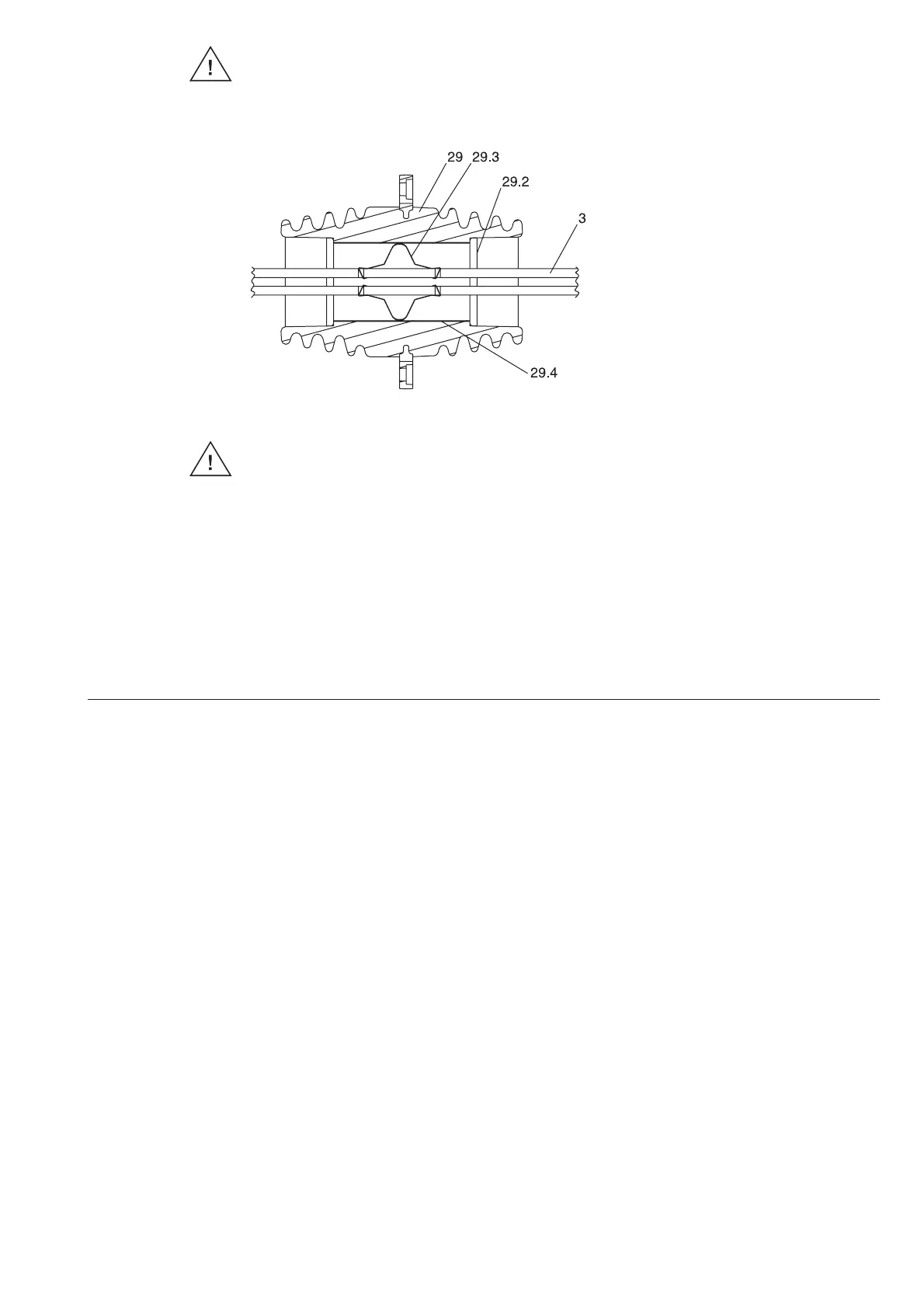
Always check that there is good contact between the metal tube in the bushing and the busbar
via contact spring 29.3. Ensure that the contact spring is in the correct position! (figure 78).
Figure 78: 24 kV panels - detail of the busbar bushing, sectional view
3 Busbar
29 Busbar bushing
29.2 Busbar support for double conductor
29.3 Contact spring
29.4 Metal tube
Important note:
The contact springs 29.3 must be inserted
during the installation of busbars. These contact springs make the connection between the busbar 3 and the metal tube
29.4 and prevent damage caused by partial discharges inside the bushing on live busbars.
Always check that there is good contact between the metal tube 29.4 in the bushing and the busbars via the contact spring.
5.7 Installation of the top-mounted boxes
For transport reasons, attachments to the panels are not completed at our works. However, they are
pre-mounted as far as possible.
5.7.1 Voltage transformer for busbar metering
• Top-mounted box 79 (figure 81) with screw fixing material in the set of bags “Top-mounted box for
metering” must be mounted on the busbar compartment.
Notes
- In panels without busbar bushing plate 28, the partition between the busbar compartment and the
top-mounted box is necessary. They are installed at the works in the top-mounted box;
- As far as equipment with busbar partitioning is concerned (i.e. with bushing plate 28), the space
between the busbar compartment and the top-mounted box must remain open for purposes of
pressure relief;
• Connecting bars 2.2 with branch conductors 2 at the junction point must be screwed together
according to figures 79 and 80. However, if necessary, the additional spacer plate 3.2 or 3.3 and
threaded plate 3.4 or 3.8, as well as the screw fixing material from the “top-mounted box for metering”
set of bags must be used;
• Insulating cover 58 must be brought into position as is described in section 5.4;
• Intermediate box 79.1, with the screw fixing material from the “top-mounted box for metering” set
of bags must be mounted on the control cabinet. Conduction tube 79.2 must be positioned and
inserted in reducer rings 79.3;
• Secondary circuits from the voltage transformers must be led to the terminal strips and connected
according to the cable core markings and circuit diagram.

 Loading...


