39
5.4. Installation of the bushing
Before fixing the panels side by side (according the general drawings) bushings 29 (12÷24 kV) must
be fixed (for switchgear with busbar barriers only; refer to the table on page 13).
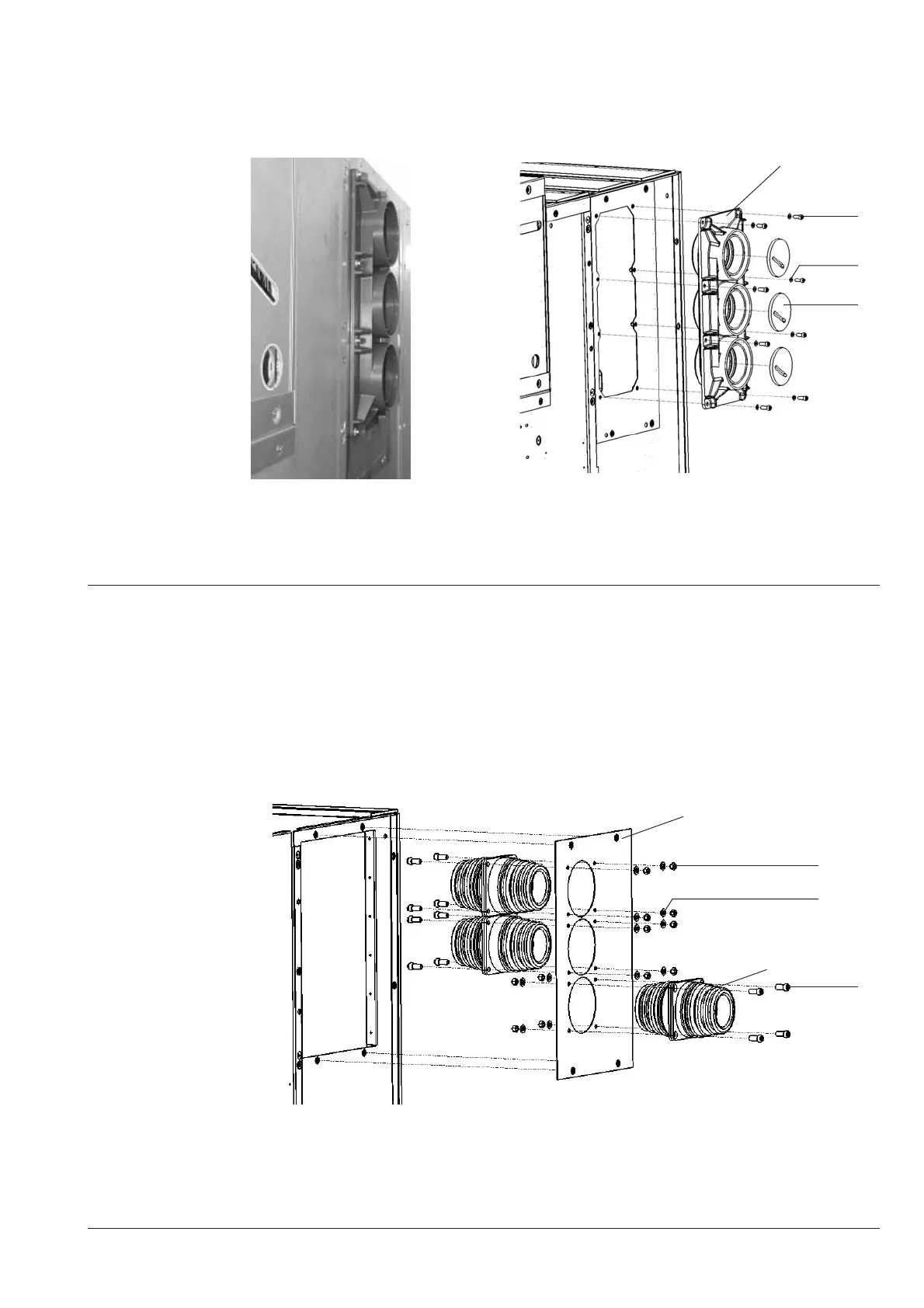
5.4.1 Bushing of 12/17,5 kV panels
Figure 61: 12/17.5kV panels - fixing bushings
29 nr. 1 bushing 31 nr. 8 M8 washer
30 nr. 8 8x25 screws 32 nr. 3 Rubber partition (busbar support)
5.4.2 Bushing of 24 kV panels
Assembly procedure for bushings – main (upper) busbar system:
• Insert bushing 29 for the lower busbar into bushing plate 28 from the right side, and the middle and
upper one from the left side (figure ).
Lower bus-tie system:
• Insert bushing 29 for the lower rear bus-tie into bushing plate 28.2 from the right side in contrast to
the procedure for the other two bushings (see Figure 8).
Figure 62: 24 kV panels - fixing bushings
28 nr. 1 bushing plate 35 nr. 12 8x25 screws
29 nr. 3 bushing 36 nr. 12 M8 washer
37 nr. 12 M8 die
30
29
31
32
37
28
36
35
29

 Loading...


