98
18.2 18.1 S9 S8 10.3
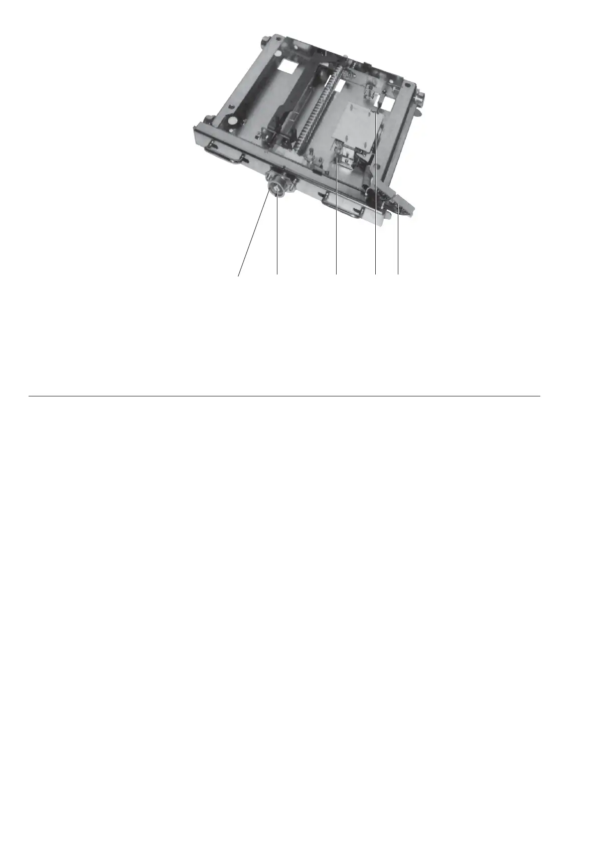
Figure 151 Withdrawable assembly (truck) for circuit-breaker with auxiliary devices.
S8 Test position indicator
S9 Service position indicator
10.3 Control circuit plug connector for withdrawable assembly
18.1 Square rod
18.2 Hole for shaft insertion lever
7.5.5 Testing interlock conditions
1. The withdrawable part must only be movable from the test/disconnected position into the service
position when the circuit-breaker is open and the earthing switch is open.
Check the following conditions individually:
• With the circuit-breaker closed, insertion of the withdrawable part towards the service position
must be locked after only half a turn of the crank in the clockwise direction, and it must not be
possible to switch on the travel motor on motor-operated withdrawable parts;
• With the earthing switch closed, insertion of the withdrawable part towards the service position
must be locked after only two clockwise turns of the crank, and it must not be possible to switch
on the travel motor on motor-operated parts.
Use no force! Also see the note in chapter 6.2.1!
2. The withdrawable part must only be movable from the service position into the test/disconnected
position with the circuit-breaker open.
Check this condition as follows:
• With the circuit-breaker closed, withdrawal movement of the withdrawable part must be locked
after only half a turn of the crank in anti-clockwise direction, and it must not be possible to switch
on the travel motor on motor-operated withdrawable parts.
3. Closing of the circuit-breaker must only be possible when the withdrawable part is in the defined test/
disconnected position or service position.
The control wiring plug 10.2 (figure 152) must previously have been inserted.
Check this condition as follows:
• It must not be possible to close the circuit-breaker with the withdrawable part in any position
between the test/disconnected position and the service position.
Enabling of switching when the withdrawable part moves into the service position is carried out
electrically by operation of auxiliary switch S9 (figure 151) in the withdrawable assembly, and
slightly earlier mechanically - this corresponds to a position approximately half a turn of the crank
before the stop;
• For movement into the test/disconnected position, the same enabling conditions apply in the
same way, in this case by means of auxiliary switch S8 in the withdrawable assembly.

 Loading...


