61
Range
voltage
(kV)
12
12/17.5
24
Panel
width
(mm)
550
650
800
1000
800
1000
Max. number
of parallel cables
in phase
3
3
1)
6
2)
3
1)
6
2)
Max. cross-
section of cables
(mm
2
)
600
630
500
Range of
cable clamp
(mm)
35 - 54
Range of
reducer ring
(mm)
27 - 62
Connection of cables in typical panels:
1) In the case where there are removable voltage transformers on the truck, or surge arresters are used, the number of parallel cables
is reduced to a max. of 2 per phase.
2) In the case where there are removable voltage transformers on the truck, or surge arresters are used, the number of parallel cables
is reduced to a max. of 4 per phase.
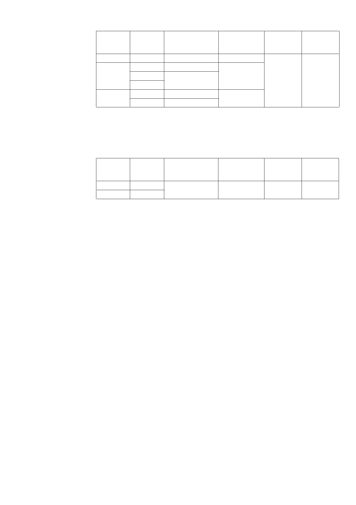
Cable connection in the panel with switch-disconnector
Range
voltage
(kV)
12/17.5
24
Panel
width
(mm)
800
1000
Max. number
of parallel cables
in phase
1
Max. cross-
section of cables
(mm
2
)
240
Range of
cable clamp
(mm)
35 - 54
Range of
reducer ring
(mm)
27 - 62
Important note
Connection with single-core plastic insulated cables is presumed in the typical panels. In the case of
any atypical cable connections or of special cables (e.g. three-core cables, cables with paper or special
insulation etc.), an agreement must be reached between the customer and manufacturer.
Mounting procedure for power cables:
• Power cables must be inserted, cut to length and stripped;
• Reducer rings 17.2 (figure 100) must be adapted to the cable diameter and fitted onto the cable;
• Cable sealing ends must be prepared and mounted on cable cores according to manufacturer’s
instructions;
• Cable eyes must be connected to the prepared connections bars 23 with strain relief;
• Earthing of cables must be connected;
• Individual parts of the floor covering must be mounted;
• Reducer rings 17.2 must be moved down so that nuts in the rings fit into the corresponding recesses
in the floor coverings. In this way, the cable passages are sealed;
• Cables must be fastened in the prepared cable clamps 21 (the maximum tightening torque applicable
to the clamp screws is 9 +2 Nm).
5.9.2 Control cables
The control cables are conveyed into the panel through the control wiring duct 1.2 on the left-hand panel
side.
Mounting procedure:
• Insert the cables into the control wiring duct 1.2 (figure 2) on the left-hand side. The duct is covered
by covers 43.1, 43.2 (figure 59);
• Fasten the control cables at the top end of the duct, strip the insulation and convey cable control cores
into the low voltage compartment D, after the terminal strip frame has been swung up (figure 107);
• Connect control cables to the terminal strip according to the circuit diagram;
Make the control wiring connections to adjacent panels using bushing 24 (figure 59).

 Loading...


