EasyManuals Logo

ABB UniGear ZS1 Instruction Manual

ABB UniGear ZS1
106 pages
To Next Page IconTo Next Page
To Previous Page IconTo Previous Page
Page #57 background imageLoading...
Page #57 background image
55
Figure 85: Schematic diagram of the pressure relief duct. The components are assembled panel by panel and bolted
together with overlaps at the panel joints.
50 pressure relief duct
1) If the switchgear is equipped with a pressure relief duct, the pressure relief flap for the cable connection
compartment is fixed to the rear side of the panel and will open to the front (into the duct) in case of an
arc fault.
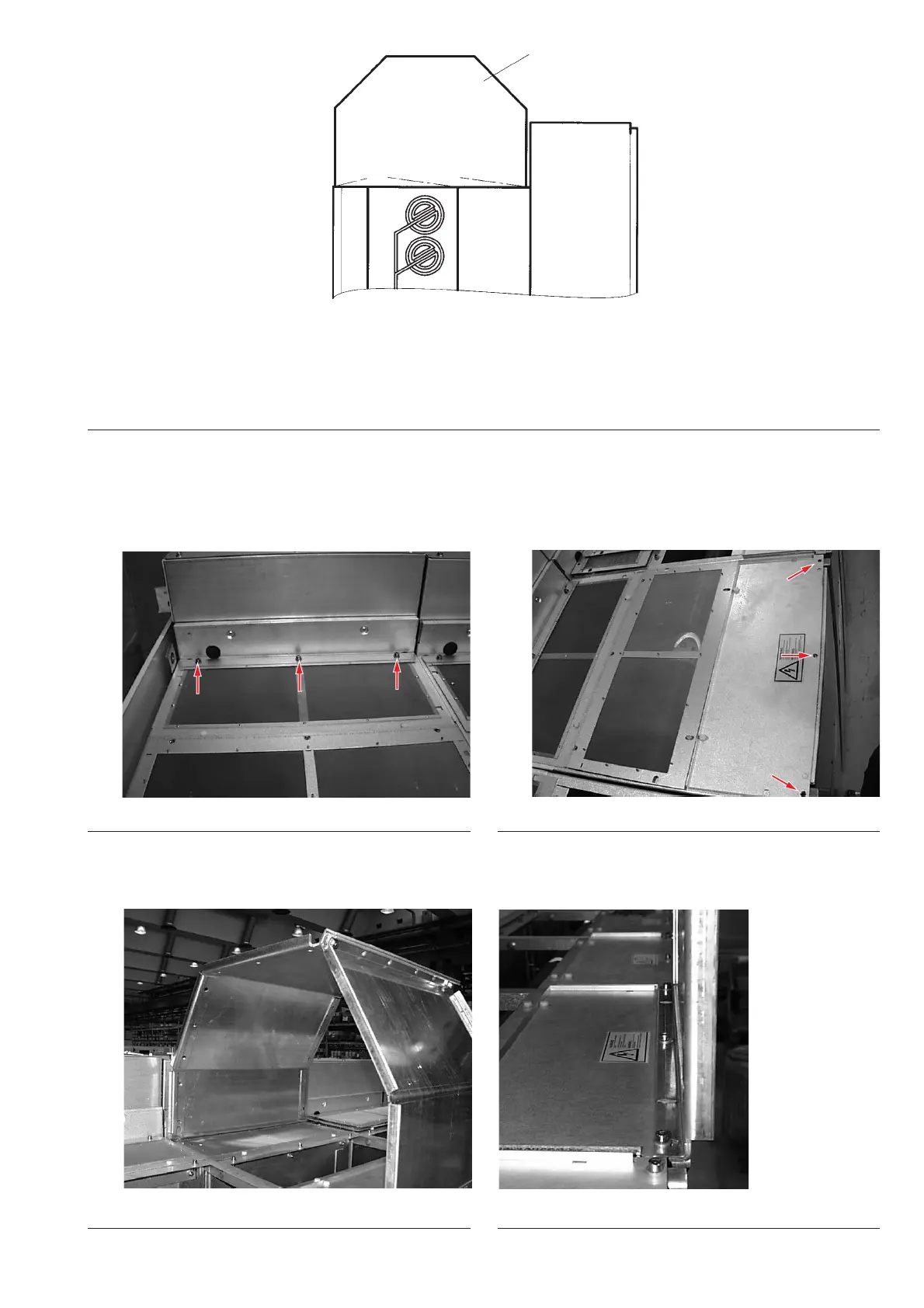
5.8.1 Standard gas duct
Once that the panels are fixed between them and to the floor, it is possible to start to fix the gas duct
on the top of the switchgear. Every panel have three fixing points in the front part (figure 86) and three
fixing points on the rear part (figure 87).
Figure 86: Fixing points on the front.
With nr. 6 screws 8x20 and nr. 6 washer M8, fix the front and rear part of the gas duct sheets
(figures 88, 89).
Figure 87: Fixing points on the rear.
Figure 88: Front sheet. Figure 89: Rear sheet.
1)
50

Table of Contents

Other manuals for ABB UniGear ZS1

Questions and Answers:

Question and Answer IconNeed help?

Do you have a question about the ABB UniGear ZS1 and is the answer not in the manual?

ABB UniGear ZS1 Specifications

General IconGeneral
Rated Voltageup to 24 kV
Rated Currentup to 4000 A
Frequency50/60 Hz
Rated Short-Circuit Breaking Currentup to 50 kA
Rated Peak Withstand Currentup to 125 kA
InsulationAir-insulated
Type of SwitchgearMetal-clad
Rated Short-time Withstand Currentup to 50 kA for 3s
Internal Arc ClassificationIAC AFLR
Protection DegreeIP4X
Busbar SystemSingle and double busbar
Type Tested AssemblyIEC 62271-200
DimensionsVaries depending on configuration
WeightVaries depending on configuration

Related product manuals