4
2. Technical data
2.1 Electrical data
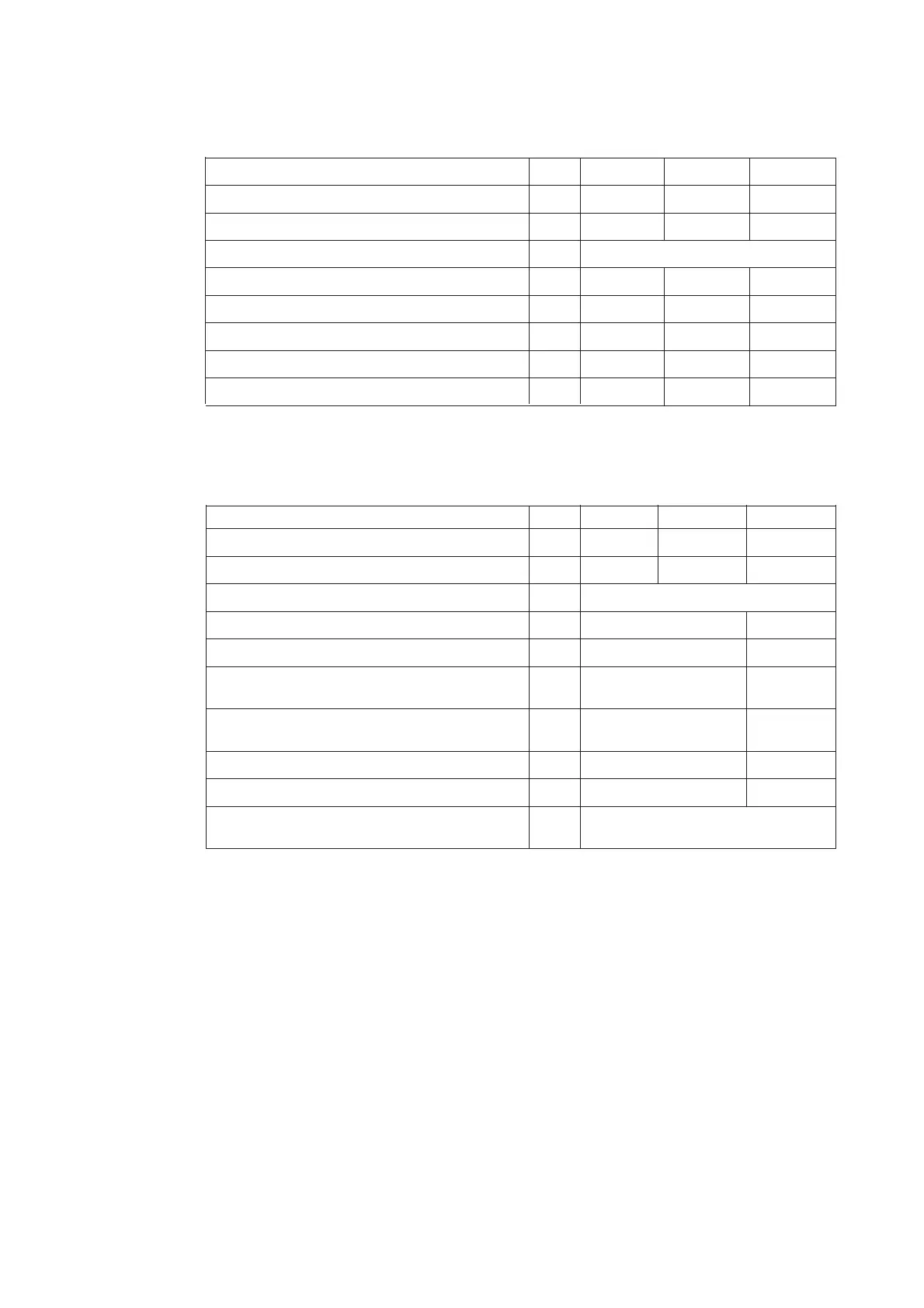
2.1.1 Main parameters for panels with circuit-breakers
Rated voltage kV 12 17.5 24
Rated power frequency withstand voltage kV 28 38 50
Rated lightning impulse withstand voltage kV 75 95 125
Rated frequency Hz 50/60
Rated current of busbars A …4000 …4000 …3150
Rated current of circuit-breaker branches A …4000 …4000 …2500
Rated peak withstand current
1)
kA …125 …125 …80
Rated short-circuit breaking current of circuit-breaker kA …50 …50 …31,5
Rated short- time current 3 s
1)
kA …50 …50 …31,5
1)
The short-circuit withstand capacity of the instrument transformers must be taken into account separately.
For individual switching device data, see the instruction manual for the relative switching device, as
listed under 7.1.
Rated voltage kV 12 17.5 24
Rated power frequency withstand voltage kV 28 38 50
Rated lighting impulse withstand voltage kV 75 95 125
Rated frequency Hz 50/60
Rated current of busbars A ...4000 ...2500
Rated current of branches A ...630 ...630
Rated breaking current of switch-disconnector
A ...630 ...630
(power factor = 0.7)
Rated short-time withstand current of
switch-disconnector 1s
1)
kA ...25 ...20
Rated short-circuit making current kA ...40 ...38
Rated peak withstand current kA ...62.5 ...62.5
Auxiliary voltage V DC 24, 48, 110, 220;
AC 110, 230
1)
The short-circuit withstand capacity of the instrument transformers must be taken into account separately.
2.1.2 Main parameters for panels with NALF switch-disconnectors
2.2 Resistance to internal arc faults
The fault withstand capacity is as follows: 12 kV - 50 kAx 1s
17.5 kV - 50 kA 1s
24 kV - 31,5 kA 1s
The switchgear units have been tested according to IEC 62271-200 standard (appendix AA, class A,
criteria 1 to 5) and also to PEHLA recommendation no. 4.
In individual cases, depending on the configuration of the switchgear panels and/or the switchgear
room conditions (e.g. low ceiling height), additional measures may be necessary to ensure compliance
with criterion 5.

 Loading...


