66
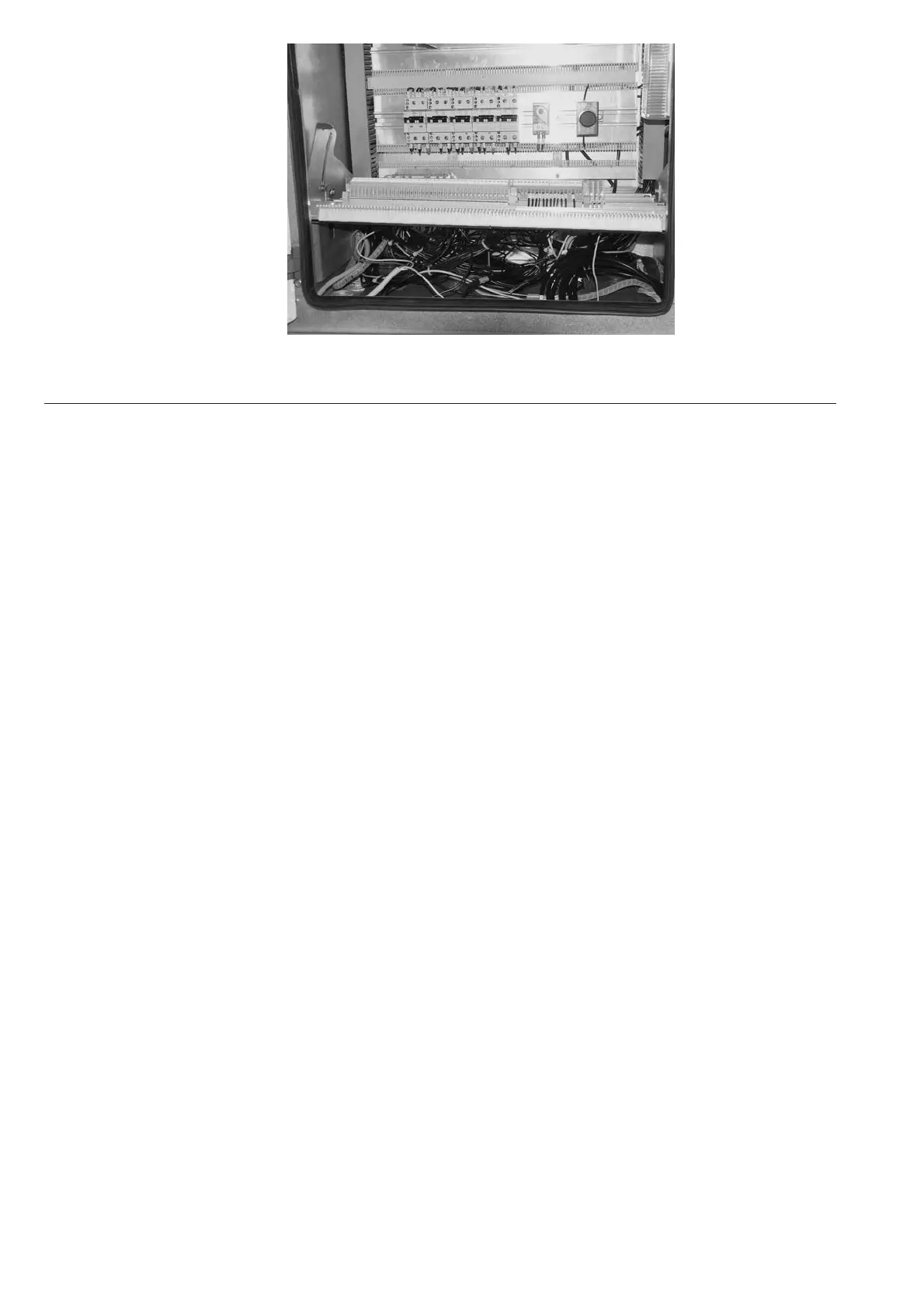
Figure 107: Terminal frame swung up for connection works
5.10 Earthing the switchgear
• Connect main earthing bar 19 (figure 101) with connections 19.1 provided in every panel.
• Protection wiring connection of the floor frame or the erected raised false floor respectively, should
be made.
• Connect the earthing conductor coming from the earth electrode, preferably via a removable bolted
connection for testing purposes, to the main earthing bar 19 of the switchgear.
5.11 Laying the ring circuits
The ring circuits are supplied rolled up in a bundle in the control cabinet or in the accessories. They
are marked and fitted with ferrules or connectors at both ends. Openings are provided in the side walls
of the control cabinet for these lines to be looped through from panel to panel.
5.12 Final erection work
• Check painted areas of the switchgear for possible damage, touching up where required (also see
section 7.4.1);
• Check bolt connections and tighten where required, in particular all those carried out during on-site
erection of the busbars and earthing system;
• After the lifting eyebolts have been removed, the Ith limiter auxiliary switch (if delivered) must be
mounted and adjusted:
- The auxiliary switch holder is fixed by means of screws 49.5 in the panel (figure 28);
- The auxiliary switch holder must be positioned horizontally (figure 28);
- The control pin of the auxiliary switch must be moved to the centre of the hole in the pressure relief
flap;
- Adjust the auxiliary switch according to figure 28;
- If the auxiliary switch is mounted and adjusted according to the above instructions, checking during
regular inspections is not necessary;
• Clean the switchgear thoroughly;
• Remove all foreign bodies from the panels;
• Correctly replace all coverings, etc. removed during erection and connection;
• In the enclosure, any remaining openings must be closed if they are no longer needed;
• Check the isolating contacts and interlocking mechanisms for smooth motion, and grease again with
mechanical grease where necessary (see section 7.4.1 and 7.7.2);
• Withdrawable circuit-breaker parts must be inserted and the control wirings connected;
• Panels doors must be properly closed.

 Loading...


