12
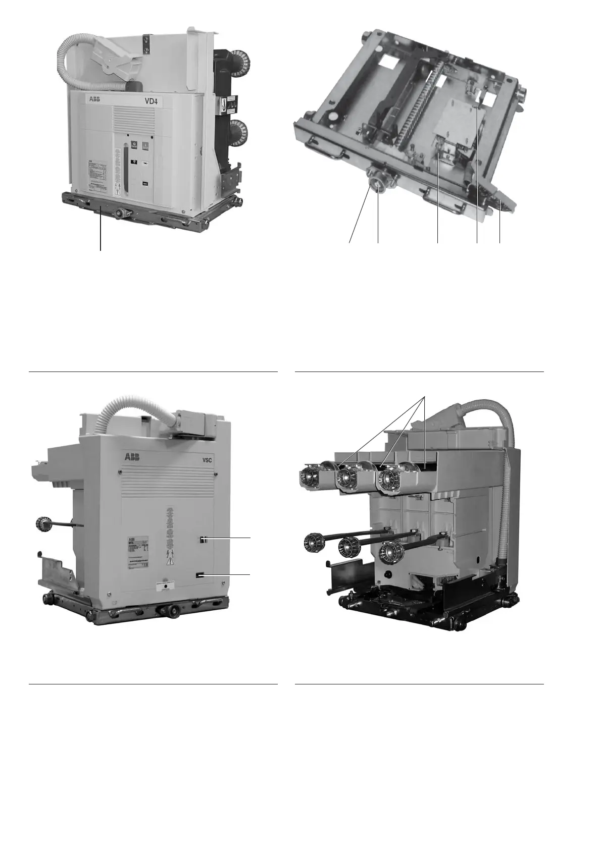
18.2 18.1 S9 S8 10.3
91.15
91.14
91.13
13.15
Figure 9: Withdrawable part with circuit-breaker, type
VD4, operating mechanism side
13.15 Withdrawable assembly
Figure 11: V-Contact VSC type vacuum contactor – front
view
91.13 Signalling device ON/OFF
91.14 Operating cycle counter
Figure 10: Withdrawable assembly for circuit-breaker,
with auxiliary switches
S8 Test position indicator
S9 Service position indicator
10.3 Control wiring plug connector for
Withdrawable assembly
18.1 Square spigot
18.2 Hole in spindle for insertion lever
spindle
Figure 12: V-Contact type vacuum contactor – pole side
91.15 MV fuses
91.13 Signalling device ON/OFF
91.14 Operating cycle counter
3.3.4 Cable connection compartment (Figure 2)
The cable compartment contains current transformers 7, fixed and withdrawable voltage transformers
8, and earthing switch 6, according to individual operating requirements in each case.10
The cable compartment is constructed for installation of three current transformers. Should all three
current transformers not be required, dummies will be installed in their place, using the same
installation and connection procedures.

 Loading...


