18
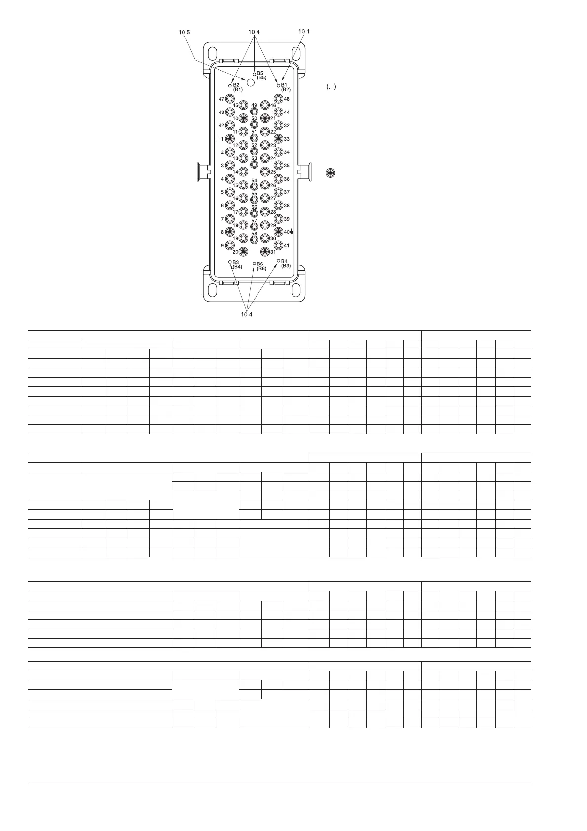
Figure 23: Control wiring plug connector coding, shown for a 58 pole connector
10.1 Control wiring socket
10.4 Centring strinking tabs
10.5 Bore for actuating pin of the control wiring plug for controlling the auxiliary switch
Coding
The corresponding coding designation for the control
wiring plug is given in brackets (10.2)
The coding pins can be fitted in the control wiring
socket (10.1) and/or in the control wiring plug (10.2).
Basic design
The number of sockets is optional, but the basic
assignment is 1, 8, 10, 20, 21, 31, 33 and 40.
Sockets and pins can be mixed as required in the
control wiring socket (10.1) and control wiring plug
(10.2).
Circuit-breakers and contactors Plug pin coding (apparatus) Socket hole coding (panel)
12-17.5 kV 650 mm 800 mm 1000 mm B1 B2 B3 B4 B5 B6 B1 B2 B3 B4 B5 B6
400 A V
•• ••
630 A VD4 VM1 HD4
•• ••
1250 A VD4 VM1 HD4 VD4 VM1 HD4
••
1600 A VD4 VM1 HD4 VD4 VM1
•• • •
2000 A VD4 VM1
••
2500 A VD4 VM1 HD4
••••
3150 A VD4 VM1 HD4
•• ••
3600 A VD4 VM1 HD4
•• ••
4000 A VD4 VM1 HD4
•• ••
Isolating trucks Plug pin coding (apparatus) Socket hole coding (panel)
12-17.5 kV 650 mm 800 mm 1000 mm B1 B2 B3 B4 B5 B6 B1 B2 B3 B4 B5 B6
400 A
630 A 17.12.32
1250 A
•• ••
1600 A 17.20.50
2000 A
•• • •
2500 A 17.25.50
••• •
3150 A
•• ••
3600 A 17.32.50
•• ••
4000 A
•• ••
Circuit-breakers Plug pin coding (apparatus) Socket hole coding (panel)
24 kV 800 mm 1000 mm B1 B2 B3 B4 B5 B6 B1 B2 B3 B4 B5 B6
630 A VD4 VM1 HD4 VD4 VM1
•• ••
1250 A VD4 VM1 HD4 VD4 VM1
••
1600 A VD4 VM1 HD4
•• • •
2000 A VD4 VM1 HD4
••
2500 A VD4 VM1 HD4
••••
Isolating trucks Plug pin coding (apparatus) Socket hole coding (panel)
24 kV 800 mm 1000 mm B1 B2 B3 B4 B5 B6 B1 B2 B3 B4 B5 B6
630 A
1250 A
24.12.25
•• ••
1600 A
2000 A 24.25.25
2500 A
••• •

 Loading...


