37
The individual installation stages are as follows:
• Remove withdrawable parts 13 (figure 2) from the switchgear panels and store them with suitable
protection;
• Dismantle lifting eyebolts 1.5 (figure 29);
• Transport the switchgear panels to the prepared installation point following the sequence shown on
the switchgear plan;
• Remove vertical partitions 9 in front of the busbar compartments by releasing the fixing screws;
• Release the fixing screws and draw out horizontal partition 20 below the withdrawable part travel
rails;
• Release and remove floor cover 17;
• Remove covers 43.2 and 43.3 (figure 59) from the vertical control wiring ducts at the front right and
left of the panel.
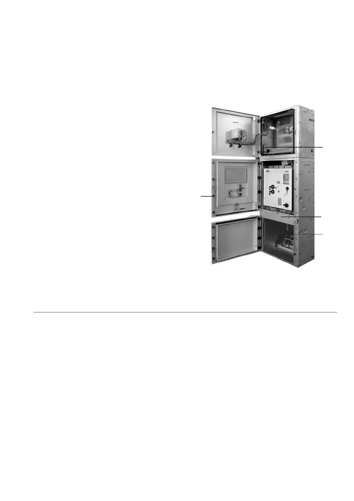
Figure 59: View into the high voltage area at the front
1.8 Central catch
1.11 Bore, for control wiring bushing 24
20 Horizontal partition, removable
43.1 Duct cover for external control cables in LV comp.
43.2 Duct cover for external control cables in cable comp.
43.3 Duct cover for external control cables in circuit breaker comp.
• If any top-mounted enclosures with busbar earthing switches or instrument transformers have been
removed for transport, bolt these in place in the specified position where the rear and middle pressure
relief plates would otherwise be located on the switchgear panels, and make the internal connections
again.
• Fit and screw the separate mechanism enclosures for any top-mounted earthing switches in the
specified position on the low voltage compartment with the front edge flush.
Note the correct positions of the parts fitted on the hexagonal drive shaft supplied loose, and then
remove the parts from the shaft, discarding the rubber ring at the front.
Insert the drive shaft step by step at the front of the mechanism enclosure until it is completely fitted,
threading on the individual parts in the correct positions for the open position of the earthing switch.
Secure the setting rings. Adjust the mounting positions and operating moments of the auxiliary
switches:
1. Adjust the positions of the auxiliary limit position switches in their slots in such a way that there is
a run-on of 0.5 mm in the fully operated position before the plunger reaches the stop (for safety
reasons);
2. The auxiliary limit position switch 78.4 (Figure 60) or earthing switch ON must operate immediately
after the dead centre position of the toggle spring mechanism is reached in the closing process and
the automatic quick-closing process has started;
3. The auxiliary limit position switch 78.5 for earthing switch OFF must be operated during the opening
movement of the slide (78.2) 1 mm before the tab of the slide makes contact with the armature of
the de-energised locking magnet 78.6 (Figure 60).
20
43.1
1.8
43.2

 Loading...


