70
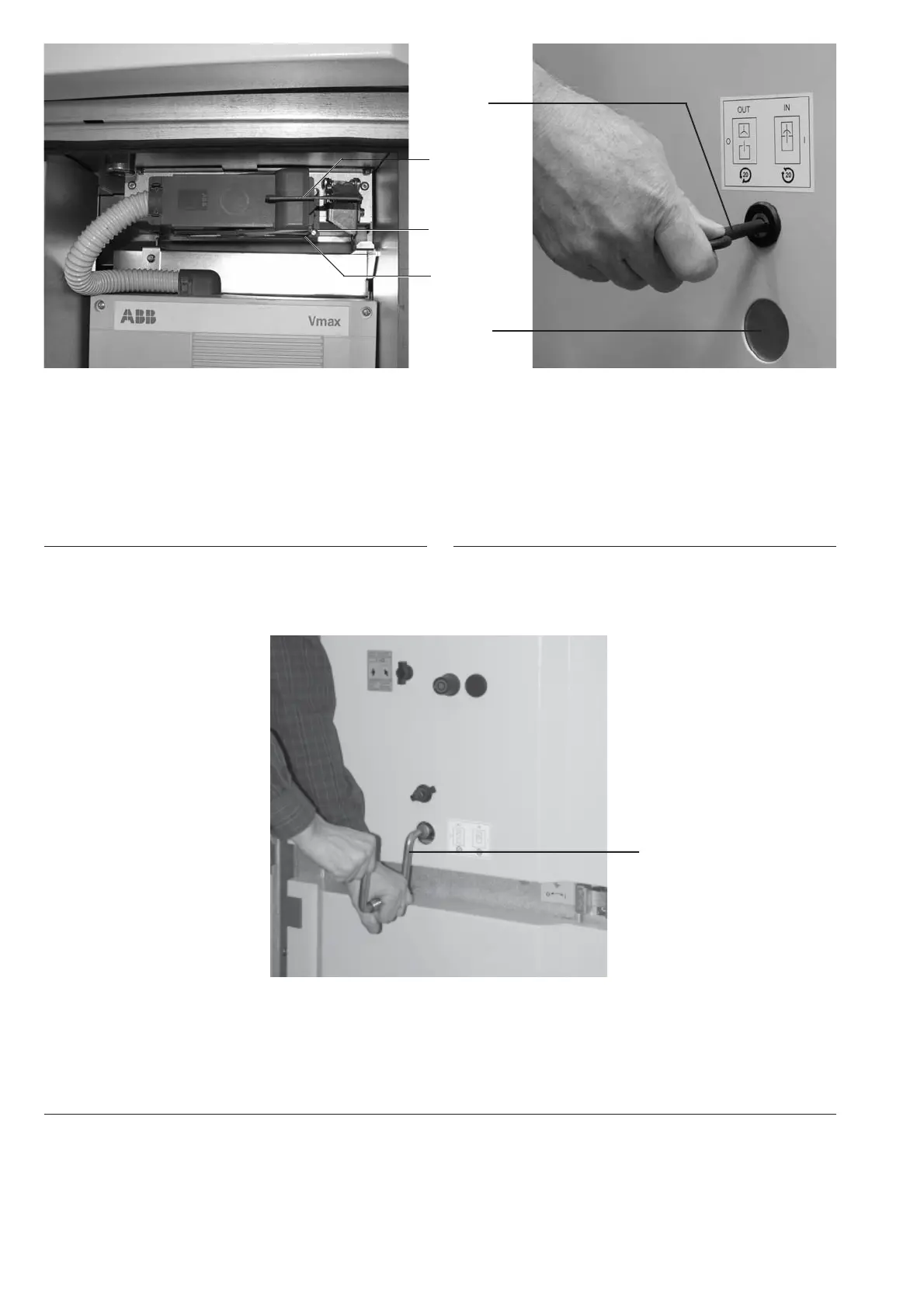
Figure 111: Control wiring plug connector blocked to it is
prevent disconnection with the withdrawable
part in the service position.
10.1 Control wiring socket
10.2 Control wiring plug
32 Interlock
Figure 113: Movement of the withdrawable part between. The test/disconnected position and the service position, clock-
wise up to the stop to the to the service position and anti-clockwise for the test/disconnected position
121 Hand
145
121.1
32
10.2
10.1
121
Figure 112: Before inserting the hand crank, necessary to
open the hole for it - turn the slide by means
of the key.
121.1 Slide
145 Double bit key

 Loading...


