96
14.6
14.7
11.4 11.3
14.1
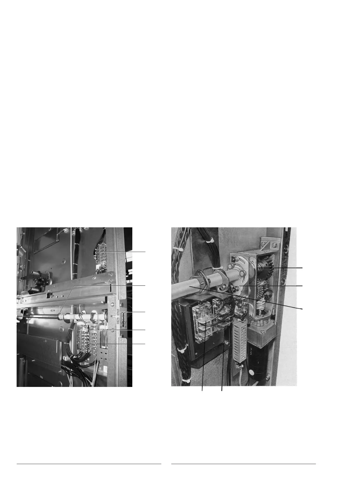
Figure 149 Manual earthing switch operating mechanism
with auxiliary contacts, side protection
removed
11.3 Q8S1 auxiliary contact – earthing
switch OFF
11.4 Q8S2 auxiliary contact – earthing
switch ON
14.1 Drive shaft (earthing switch)
14.2 Sliding closure
14.3 Cam plate, adjustable
Figure 150 Earthing switch motor operator with auxiliary
contacts installed, protections removed
11.3 Q8S1 auxiliary contact – earthing
switch OFF
11.4 Q8S2 auxiliary contact – earthing
switch ON
14.1 Drive shaft for earthing switch
14.6 Locking disk
14.7 Cam
2. Motor operator for the earthing switch
• Disconnect the terminals;
• Loosen the grub-screw in the set collars;
• Withdraw operating shaft 14.1;
• Observe the position of locking disc 14.6 relative to cam 14.7;
• Replace the motor operator;
• Slide the operating shaft through from the front;
• Observe the position of locking disc 14.6 relative to cam 14.7;
• Tighten the grub-screw in the set collars;
• Connect the control wiring;
• Set the operating mechanism manually to an intermediate position and only then perform a test run
to determine the direction of rotation;
• Ensure that the motor shuts down correctly in the final positions!
Note
The auxiliary switches of the interchangeable groups are adjusted at the works.
When final installation of the earthing switch and operator takes place on site, it may be necessary to
carry out further precise adjustment of the auxiliary switch. In this case, the following should be taken
into account:
• There must be a run-on of 0.5 mm in the fully operated position before the plunger reaches the stop
(for safety reasons);
• Auxiliary limit switch 11.4 (figure 149) for earthing switch ON must be operated immediately after
the dead centre position of the toggle spring mechanism has been reached in the closing process
and the automatic quick-closing process has started;
• Auxiliary limit switch 11.3 for earthing switch OFF must
a) be operated on earthing switches with manual mechanisms during the opening movement of slide
14.2 before half of the hexagonal shaft has become visible, or 1 mm before the tab of the slide
makes contact with the armature of the de-energised locking magnet;
b) be operated on earthing switches with motor operator (no slide 14.2 fitted) immediately after the
toggle spring mechanism has passed the dead centre position during rotation to the OFF position.
11.3
11.4
14.2
14.3
14.1

 Loading...


