Ins p ect i o n | C h ec k i ng t h e b rak e on t h e c h a in hoi st
37
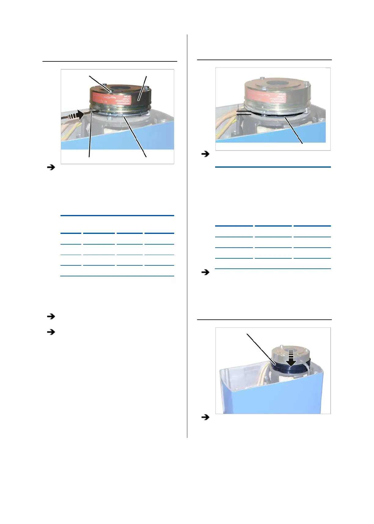
MEASURING THE AIR GAP
Magnet body
Feeler gauge Anchor plate
Insert the feeler gauge next to one of the
hexagon head screws in the air gap between
magnet body and anchor plate and measure
the distance.
If the air gap has reached the maximum width
of the operating range, adjust the brake. See
“Setting the air gap on the brake”, page 67.
Size Air gap
target value
Maximu
air gap
Minimum
air gap
GM2 0.25 mm 0.6 mm 0.2 mm
GM4 0.3 mm 0.6 mm 0.2 mm
GM6 0.35 mm 0.6 mm 0.3 mm
GM8 0.35 mm 0.6 mm 0.3 mm
If the width of the air gap is within the permitted
range but usage behaviour leads to the
expectation that the air gap will be wider than
permitted before the next regular inspection,
the air gap must be readjusted now.
Repeat the steps for all hexagon head screws
(3x).
Clean the entire brake with compressed air.
MEASURING BRAKE LINING
THICKNESS
Brake rotor
Check the thickness of the brake lining with a
calliper.
Size
Brake lining
thickness, new
Brake lining
thickness, minimum
GM2 7.5 mm 4.5 mm
GM4 8.5 mm 5.5 mm
GM6 10.5 mm 7.5 mm
GM8 10.5 mm 7.5 mm
If the brake rotor is thinner than permitted,
replace the brake rotor. See “Replacing the
brake rotor ”, page 71.
COVERING THE BRAKE
Dust guard ring
Pull the dust guard ring over the brake.