143
Volume Input /
Output
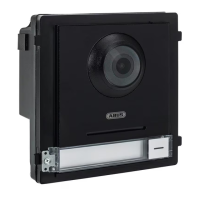
Audio parameter settings for video door
module. (See Installation and operating
information)
Dial
Determines the apartment assignment for
the call button on the door video module
itself. A “1” will be under “room no.” as
standard from the factory. This means the
monitor is called with apartment number 1.
Motion
Detection
Motion detection setting in connection with
ABUS NVR. (Please only set up and
configure the motion detection directly via
BUS NVR)
Intercom
Protocol
Not used
Sub Module Overview of connected extension modules
e.g.: TVHS20020, TVHS20030,
TVHS20040
“Network” section
Local NetCfg IP address of video door module. (IP
address, subnet mask, standard
gateway)
Port: 8000 is needed to connect to an
ABUS NVR
http Port is not needed as there is no web
interface
Linked
Network
Configuration
Menu item is not used on a main video
door module.
Main Outdoor IP Address: Is used to
assign the main door station to a back
door. (See Installation and operating
information)
FTP
Configuration
Not used
Advanced
Settings
Configuration of DNS server address for
door video module
“Display” section
Video
Paramete
Settings for image parameters (brightness,
contrast, saturation)
Video Display Settings for OSD display (camera name,
date, time, text position)
Video&Audio Stream parameter settings for video door
module camera. Attention: We do not
recommend modifying settings.
Back Light
Compensation
BLC function options for compensating for
back light.