42
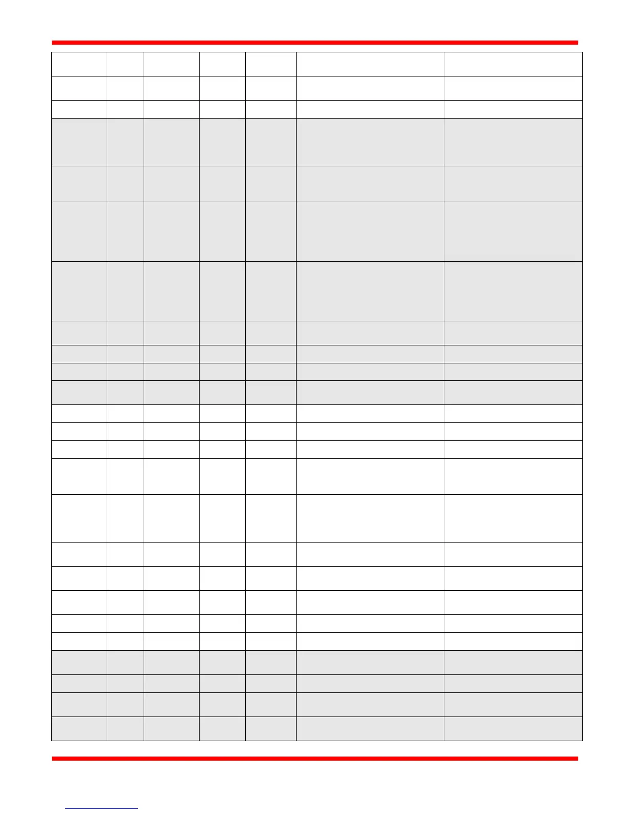
10007 7 6 0 6 POC, IGN1 relay output
1 = POC IGN1 relay output
1 = POC "minus" terminal is
High (12VDC present)
input is High (12VDC
present, shutdown sensor
10010 10 9 1 1 Remote Start/Stop input 1 = Remote Start/Stop
switch is On/Closed
10011 11 10 1 2 HT input: AUX 2 terminal
"minus" input (output of TC2
"R2" relay)
1 = High Temp R2 relay
output is High (12VDC is
present, not in High Temp
shutdown), 0 = high temp
10012 12 11 1 3 Output of TC1 "R1" relay
(input to POC relay)
1 = "Low" Temp R1 relay
output is High (12VDC is
present), 0 = TC1 temp is in
shutdown (if in Intermittent
10013 13 12 1 4 PWR fail condition (only on
1 = Latch is on presently
1 = Latch is on presently
High Gas SD/SD latch
condition
1 = High Gas SD Latch is
on presently
Thermocouple 1 open/fault
1 = TC fault, 0 = no fault
Thermocouple 2 open/fault
1 = TC fault, 0 = no fault
condition
1 = Modbus Remote Stop is
active (CSC400 is stopped
1 = Level Shutdown input is
High (12VDC present,
shutdown sensor not
IGN1 Pilot Solenoid Fault
(Short)
1 = Solenoid fault (short),
0 = no fault
(Short)
1 = Solenoid fault (short),
0 = no fault
IGN1 TMain Solenoid Fault
(Short)
1 = Solenoid fault (short),
0 = no fault
10025 25 24 3 0 (LSB) "Stop" relay output
1 = "Stop" relay is on
Thermocouple 3 open/fault
1 = TC fault, 0 = no fault
10027 27 26 3 2 AUX2 SD/SD latch condition 1 = AUX2 SD Latch is on
AUX1 SD/SD latch condition
1 = AUX1 SD Latch is on
presently