17
4. Disconnect positive (+) battery
cable.
5. Connect RED test lead to positive
(+) battery terminal.
6. Connect BLACK test lead to posi-
tive (+) battery cable.
NOTE: Do not start vehicle during this
test, because multimeter damage may
result.
7. Turn multimeter rotary switch to
10A DC (or 200 mA) position.
8. View reading on display.
• Typical current draw is 100mA.
(1mA = 0.001A)
• Refer to vehicle service manual for
manufacturers specific Engine Off
Battery Current Draw.
NOTE: Radio station presets and
clocks are accounted for in the 100mA
typical current draw.
9. Test Results.
Normal Current Draw: Display read-
ing in Step 8 is within manufacturers
specifications.
Excessive Current Draw:
- Display reading in Step 8 is well out-
side manufacturers specifications.
- Remove Fuses from fuse box one
at a time until source of excessive
current draw is located.
- Non-Fused circuits such a s
headlights, relays, and solenoids
should also be checked as pos-
sible current drains on battery.
- When source of excessive current
drain is found, service as necessary.
Cranking Voltage -
Battery Load Test
This test checks the battery to see if it is
delivering enough voltage to the starter
motor under cranking conditions.
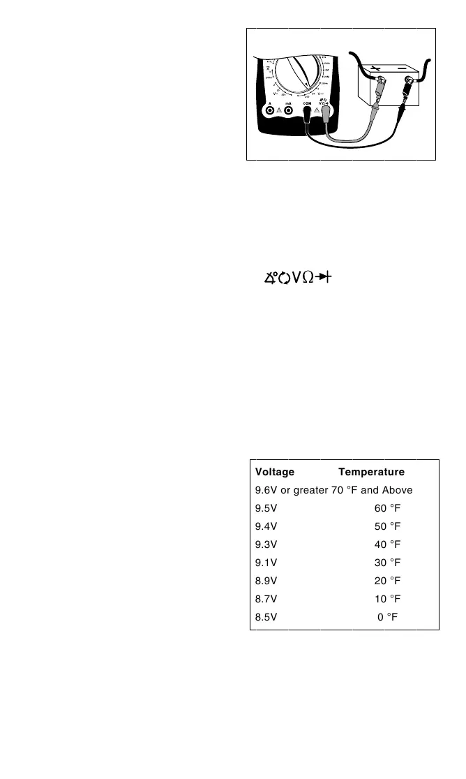
Test Procedure (see Fig. 21):
1. Disable ignition system so vehicle
won’t start.
Disconnect the primary of the igni-
tion coil or the distributor pick-up coil
or the cam/crank sensor to disable
the ignition system. Refer to vehicle
service manual for disabling
procedure.
2. Insert BLACK test lead into COM
test lead jack.
3. I nsert R ED test lead into
test lead jack.
4. Connect RED test lead to positive
(+) terminal of battery.
5.
Connect BLACK test lead to nega-
tive (-) terminal of battery.
6. Turn multimeter rotary switch to
20V DC range.
7. Crank engine for 15 seconds con-
tinuously while observing display.
8. Test Results.
Compare display reading in Step 7
with chart below.
Voltage Temperature
9.6V or greater 70 °F and Above
9.5V 60 °F
9.4V 50 °F
9.3V 40 °F
9.1V 30 °F
8.9V 20 °F
8.7V 10 °F
8.5V 0 °F
If voltage on display corresponds to
above voltage vs. temperature chart,
then cranking system is normal.
If voltage on display does not corre-
spond to chart, then it is possible that
the battery, battery cables, starting sys-
tem cables, starter solenoid, or starter
motor are defective.
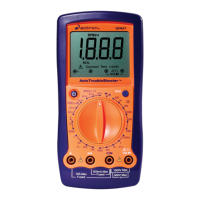
Fig. 21
Red Black
600
600
 Loading...