24
Magnetic Pick-Up Coils – Reluctance Sensors
Reluctance sensors are used whenever
the vehicle computer needs to know
speed and position of a rotating object.
Reluctance sensors are commonly used
in ignition systems to determine cam-
shaft and crankshaft position so the ve-
hicle computer knows the optimum time
to fire the ignition coil(s) and turn on the
fuel injectors. This test checks the reluc-
tance sensor for an open or shorted coil.
This test does not check the air gap or
voltage output of the sensor.
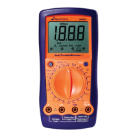
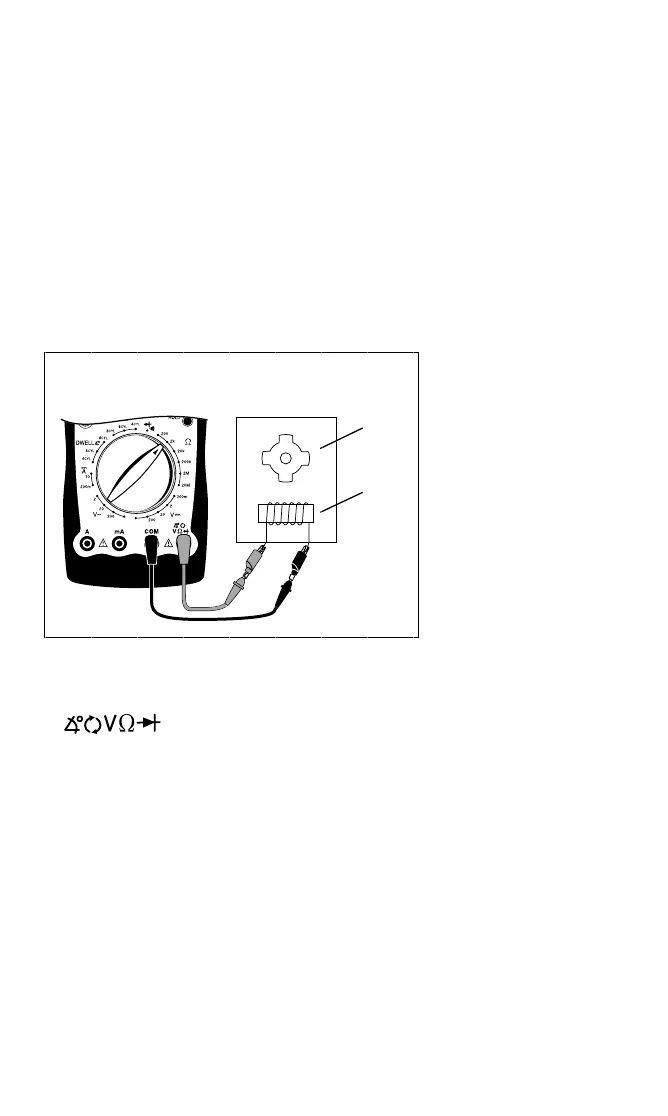
Test Procedure (see Fig. 28):
Reluctance
Sensor
Red
Black
1. Insert BLACK test lead into COM
test lead jack.
2. I nsert R ED test lead i nto
test lead jack.
Reluctor
Ring
Magnet
3. Connect RED test lead to either
sensor pin.
4. Connect BLACK test lead to re-
maining sensor pin.
5. Turn multimeter rotary switch to
2KΩ range.
6. View reading on display while flex-
ing sensor wires in several places.
• Typical resistance range is 150 -
1000Ω.
• Refer to vehicle service manual for
your vehicles resistance range.
• As you flex sensor
wires, the display
should remain steady.
7. Test Results
Good Sensor: Display
reading is within manu-
facturers specification
and remains steady
while sensor wires are
flexed.
Bad Sensor: Display
reading erratically
changes as sensor wires
are flexed or display
reading is not within
manufacturers
specification.
Fig. 28
600
600
 Loading...