30
28
Technical Specifications
Maximum Operating Pressure
Primary: 3 bar
Secondary: 10 bar
Factory Test Pressure
Primary: 4.5 bar
Secondary: 13 bar
Maximum Operating
Tem pe ratur e
90°C
Power Supply
230v 50Hz
Code
02604501 02604401
Fuel Natural gas/LPG Natural gas/LPG
Burner options type
BG2000-M BG2000-M
Input kW
20 to 69.9 25 to 107/22 to 110
Maximum output kW
18.4 to 63 23 to 96.8/20.2 to 99
Primary capacity L
108 130
Total capacity L
239 330
Heating surface area m
2
3.14 3.95
Primary circuit pressure drop mbar
46 83
DHW tank pressure drop mbar
45 180
Flue circuit pressure drop mbar
0.6 1.4
DHW connection (male BSP) Ø
1" 1"
Primary connection (female BSP) Ø
1
1
/
2
”
1
1
/
2
”
Flue connection (G) Ø mm
150 150
Flue connection options type
B23/C13/C33/C53 B23/C13/C33/C53
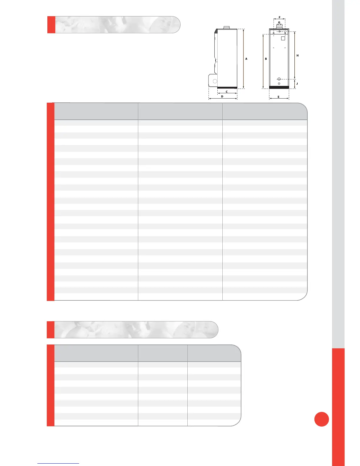
Dimensions A mm
1743 2093
Bmm
1630 2030
Cmm
678 678
Dmm
937 937
Emm
680 680
F mm 390 390
H* mm
1289 1693
Jmm
285 285
Air intake connection Ø mm
80 100
Weight empty Kg
282 335
Weight full Kg
521 665
Minimum working gas pressure mbar
20(Nat Gas)/37(LPG) 20(Nat Gas)/37(LPG)
Gas flow rate
m
3
/h 2.12 to 7.4(Nat Gas/0.82 to 2.86 (LPG) 2.65 to 11.32(Nat Gas/0.9 to 4.5(LPG)
Note : The above performances are based on the hot water being blended at point of use,
with a boiler temperature of 90°C and a domestic cold water inlet of 10°C.
Domestic Hot Water Performances
Peak flow 40°C L/10' 646 905
Peak flow 45°C L/10' 543 777
Peak flow 60°C L/10' 346 514
Peak flow 40°C L/60' 2133 3172
Peak flow 45°C L/60' 1794 2680
Peak flow 60°C L/60' 1219 1813
Continuous flow 40°C L/h 1835 2776
Continuous flow 45°C L/h 1573 2379
Continuous flow 60°C L/h 1067 1665
Reheat time to 60°C min 16 13
*The HeatMaster 101 is currently fitted with two heating flow outlets – the upper connection (recommended)
is shown by the dimension H.A second connection (compatible with the previous HM100N) is positioned 365mm lower.
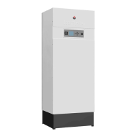
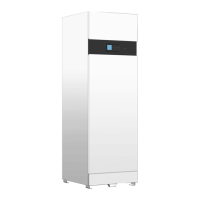
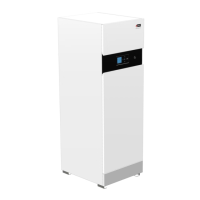
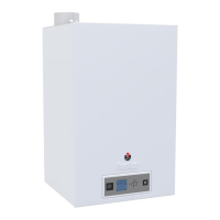
HM71
HM101
HM71
HM101
HeatMaster® 71 -101