36
34
Technical Specifications
Maximum Operating Pressure
Primary: 3 bar
Factory Test Pressure
Primary: 4.5 bar
Maximum Operating Temperature
85°C
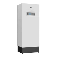
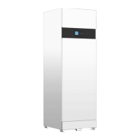
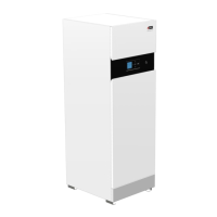
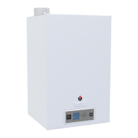
A Modulating Electric Boiler
*Outputs vary depending upon voltage – see technical manual for further clarification
Code 00078001 00078001 00078101 00078101 00078201
Nominal Output * kW 8.4 8.4 14.4 14.4 21.6
Nominal supply V 230 3 x 400 + N 230 3 x 400 + N 3 x 400 + N
Nominal supply amps 36 3 x 12 63 3 x 21 3 x 31
Total capacity L131313 1313
Primary expansion vessel capacity L 8 8 8 8 8
Primary connection (female BSP) Ø
3
/
4
”
3
/
4
”
3
/
4
”
3
/
4
”
3
/
4
”
Primary pressure drop mbar 1 1 2 2 5
Dimensions Height mm 720 720 720 720 720
Width mm 430 430 430 430 430
Depth mm 300 300 300 300 300
Weight empty Kg363636 3636
Weight full Kg 49 49 49 49 49
ETS 09
Single Phase
ETS 09
Tri-Phase
ETS 15
Single Phase
ETS 15
Tri-Phase
ETS 24
Tri-Phase
Boiler temperature with the ETS is controlled by a dual stage thermostat which is set by the user to give the desired boiler
temperature.When the boiler has heated up to within 7°C of the set temperature,the thermostat switches off one power stage and
therefore reduces the heat input.
Thanks to this simple but effective form of modulation,the ETS has longer working cycles and requires less stops and starts,thus
resulting in a more even temperature across the boiler.It also means less wear and tear on components and importantly,it uses less
power once it has reached working temperature.
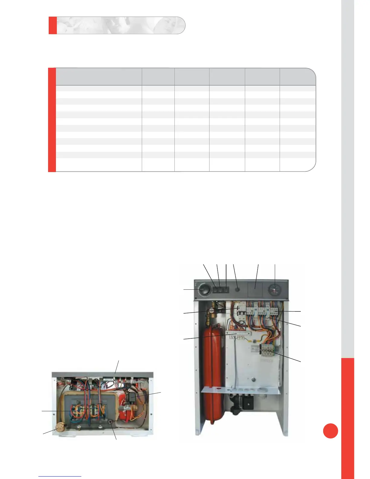
1. Control circuit connections
2. Control circuit MCB (3amp)
3. Dual stage control thermostat
4. On/off switch
5. 1st stage power level switch
6. 2nd stage power level switch
7. Manual reset high limit thermostat
8. Space for optional timeclock
9. Combined temperature and pressure gauge
10. Element supply contactor
11. Power stage delay timer
12. Power cable connections
13. Control panel
14. Primary low water pressure switch
15. Thermostats pocket
16. Automatic air vent
17. Heating elements
1
2
3
4 5 6 7 8 9
10
11
12
ETS
13
14
15
16
17