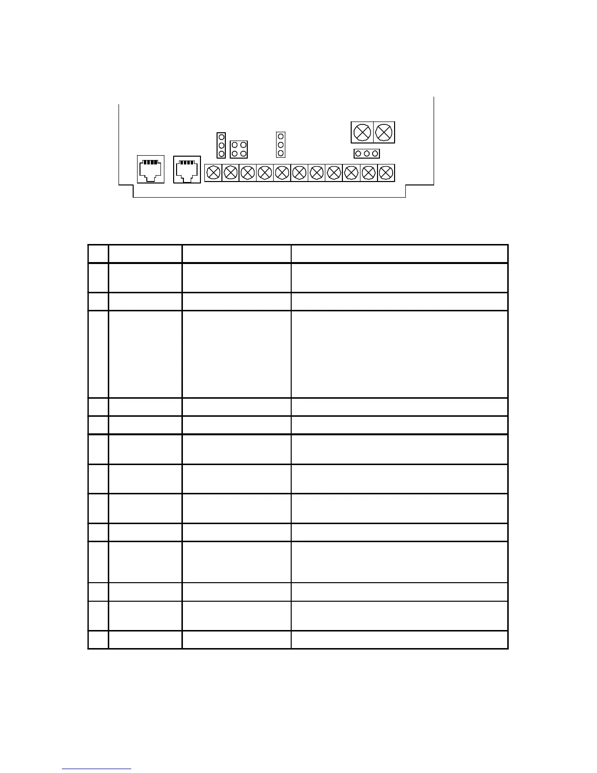
7-3 Control terminals descriptions
All terminal can connect to switch, relay, TTL or Transistor. Refer
to 8-3 for detail.
18
SPEED
A/BL C CW CCW
OUT
H M
CF
EXG 24V
J4
J5
S161
J6
MB+
MB-
HallRS485
sensor
No Symbol Terminal name Description
1 A/B Alarm output
Fault alarm contact. Set J4 jumper for A
(normal open) or B (normal close).
2 C Alarm output common Fault alarm contact C.
3 CF
Analog and digital
speed input selection
CF/EXG open : Analog speed input is from
panel VR or F306 VR. Digital speed input is
CD28 or CD34 setting. Set J5 jumper for panel
VR or F306 VR selection.
CF/EXG short : Analog speed input is from
external VR by H M L terminals. Digital speed
input is CD29 or CD35 setting.
4 CW Forward operation Forward operation / stop terminal.
5 CCW Reverse operation Reverse operation / stop terminal.
6 SPEED OUT Speed signal output
L, M model : 12 pulses/turn
H, HX model : 6 pulses/turn
7 EXG Common terminal
Common for terminal 3~6 or for external
24VDC(20mA)
8 24V External 24VDC input
+24VDC external power input. Set S161
jumper to select internal or external power.
9 H +10 VDC External VR reference voltage.
10 M Analog command input
External analog speed command input. Set J6
jumper for voltage 0~5VDC, 0~10VDC or
4~20mA.
11 L H and M common
MB- Motor brake -
24VDC, 15W, connect to magnet brake for
60~370W motor only
MB+ Motor brake +