ix MIC-770 User Manual
Contents
Chapter 1 General Introduction ...........................1
1.1 Introduction ............................................................................................... 2
1.2 Product Features....................................................................................... 2
1.2.1 General ......................................................................................... 2
1.2.2 Display .......................................................................................... 2
1.2.3 Ethernet ........................................................................................ 3
1.3 Chipset ...................................................................................................... 3
1.3.1 Functional specification................................................................. 3
1.4 Mechanical Specifications......................................................................... 4
1.4.1 Dimensions ................................................................................... 4
Figure 1.1 MIC-770 Mechanical Dimension Drawing .................. 4
1.4.2 Weight........................................................................................... 4
1.5 Power Requirements................................................................................. 5
1.5.1 System power ............................................................................... 5
1.5.2 RTC battery................................................................................... 5
1.6 Environment Specification......................................................................... 5
1.6.1 Operating temperature.................................................................. 5
1.6.2 System safety certification test temperature ................................. 5
1.6.3 Relative humidity........................................................................... 5
1.6.4 Storage temperature ..................................................................... 5
1.6.5 Vibration during operation............................................................. 5
1.6.6 Shock during operation ................................................................. 5
1.6.7 Safety............................................................................................ 5
1.6.8 EMC .............................................................................................. 5
Chapter 2 H/W Installation....................................7
2.1 Introduction ............................................................................................... 8
2.2 Jumper & Slide Switch .............................................................................. 8
2.2.1 Jumper description........................................................................ 8
2.2.2 Jumper list..................................................................................... 9
Table 2.1: Jumper List ................................................................. 9
2.3 Connectors.............................................................................................. 10
2.3.1 MIC-770 External I/O Connectors............................................... 10
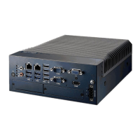
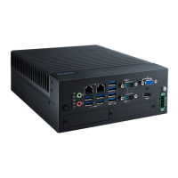
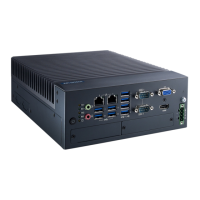
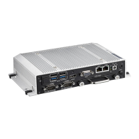
Figure 2.1 MIC-770 Front View.................................................. 10
Table 2.2: COM Connector Pin Assignments............................ 11
Figure 2.2 Ethernet Connector .................................................. 11
Table 2.3: Ethernet Connector Pin Assignments....................... 11
Figure 2.3 Audio Connector....................................................... 12
Table 2.4: Audio Connector Pin Assignments ........................... 12
Figure 2.4 USB 3.0 Connector................................................... 12
Table 2.5: USB 3.0 Connector Pin Assignment......................... 12
Figure 2.5 VGA Connector ........................................................ 13
Table 2.6: VGA Connector Pin Assignments............................. 13
Figure 2.6 HDMI receptacle connector ...................................... 13
Table 2.7: HDMI Connector pin assignments............................ 13
Figure 2.7 4-pin header ............................................................. 14
Table 2.8: Pin Assignments for Power Connector Pin Header.. 14
Figure 2.8 Power Button ............................................................ 14
Figure 2.9 LED Indicators .......................................................... 14
2.4 Installation ............................................................................................... 15
2.4.1 HDD installation .......................................................................... 15
2.4.2 Memory Installation..................................................................... 17
2.4.3 m-SATA/Mini-PCIe Installation ................................................... 17