Chapter 2 Connecting Peripherals 21
2.7 24-bit LCD display connector (CN5)
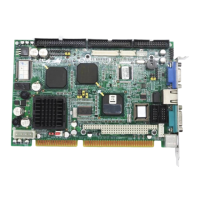
CN5 is a 40-pin dual-in-line header and is used to connect an LCD
display to the PCA-6751 Series. The PCA-6751 Series has bias
control which can be used to control the LCD signal voltage. Pin 7 of
CN5 is for LCD contrast adjustments, the LCD contrast can be
adjusted via the VR2 (located on the upper left corner of CN5).
The VGA interface is set up solely with the software utiliity provided.
Refer to Chapter 4 for details.
2.8 36-bit LCD display connector (CN6)
The PCA-6751 Series supports 36-bit LCD that must be connected to
both CN5 (40-pin) and CN6 (20-pin).
The pin assignments for both CN5 and CN6 can be found in
Appendix C.
2.9 LCD inverter connector (CN7)
The LCD inverter is connectoed to CN7 via a 5-pin connector to
provide +12 V power to the LCD display. Pin 4 of CN7 provides LCD
brightness control and can be adjusted via the VR1 (located on the
uppper right corner of CN7).
2.10 IR connector (CN8)
This connector supports the optional wireless infrared transmitting
and receiving module. This module mounts on the system case. You
must configure the setting through BIOS setup.
2.11 External speaker connector (CN9)
Connect external speakers to CN9. To activate the on-board buzzer,
set the connector so that Pins 4 and 5 are closed.
 Loading...
