45 PCI Communication User Manual
Chapter 5 Pin Assignments and Wiring
5.2 Wiring
5.2.1 RS-232 Signal Wiring
Since the RS-232 interface is not strictly defined, many devices have their own con-
nection methods, and these may ignore some signal lines or lines reserved for other
functions. It is best to refer to the user manual of your device for installation instruc-
tions. You may find the following helpful.
In general, data terminal equipment (DTE) refers to a device that communicates with
data circuit-terminating equipment (DCE). DTE examples include PCs, terminals,
and some printers; whereas DCE examples include modems, digital service units
(DSUs), printers, and lab/factory equipment.
In some situations you may be able to get by with just three lines: data on TxD, a sig-
nal ground, and a handshaking line. Examples where this would work are printer or
plotter connections, troubleshooting, and situations where you require only one-wire
communication.
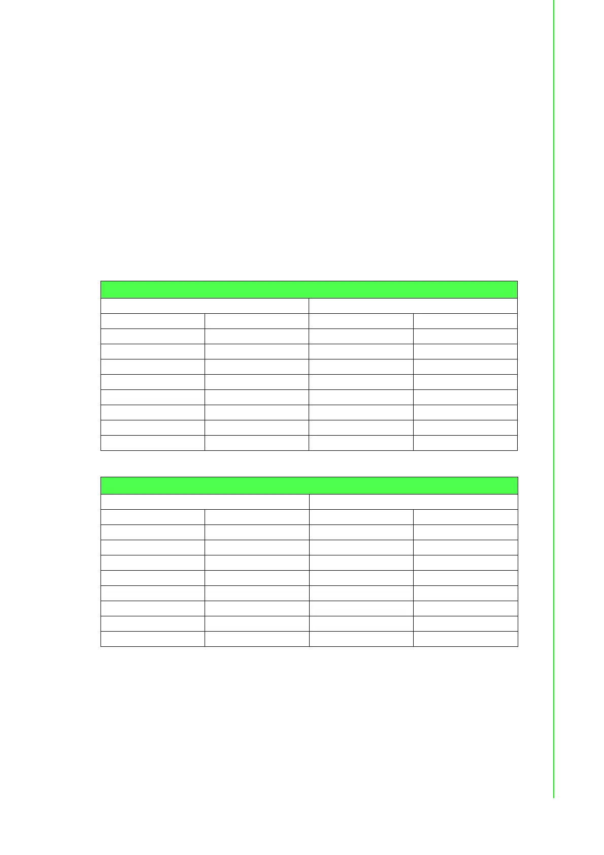
Table 5.15: Terminal or PC (DTE) Connections
DB-25 Male DB-25 Male or Female: Terminal
Pin Signal Pin Signal
2TxD3RxD
3RxD2TxD
4RTS5CTS
5CTS4RTS
6DSR20DTR
7GND7GND
20 DTR 6 DSR
8 DCD 8 DCD
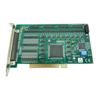
Table 5.16: Modem Connections
DB-25 Male Modem (DCE)
Pin Signal Pin Signal
2TxD3RxD
3RxD2TxD
4RTS5CTS
5CTS4RTS
6DSR20DTR
7GND7GND
20 DTR 6 DSR
8 DCD 8 DCD