PCI Communication User Manual 46
For DTE to DCE connections, use a straight-through cable (i.e., you do not need to reverse
Lines 2 and 3, Lines 4 and 5, or Lines 6 and 20 since, in general, DCE RS-232 interfaces are
reversed themselves).
Therefore, if you are not using CTS, RTS, DSR, DTR, or DCD signals, short Pins 4 and 5
together, and short Pins 6, 8, and 20 together.
5.2.2 RS-422 Signal Wiring
The RS-422 interface wiring is based on the one-on-one principle. The transmit lines
on one side connect to the receive lines on the other side (and vice versa). With RS-
422, you can transmit and receive data simultaneously (full duplex). The connections
are as follows:
Termination Resistors Setup
Termination resistors are onboard and can be selected by using a jumper for 120 or
300 Ω. Each pair of signal lines has a separate resistor (RxD+/-, TxD+/-).
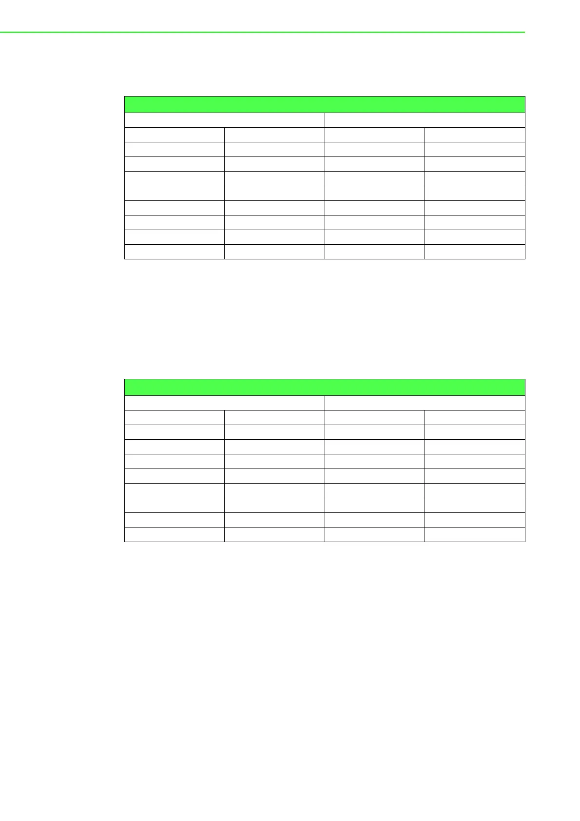
Table 5.17: Terminal Without Handshake
DB-25 Male Terminal, PC (DTE)
Pin Signal Pin Signal
2TxD3RxD
3 RxD 2 TxD
4RTS
5CTS
7GND7GND
6DSR
20 DTR
8 DCD
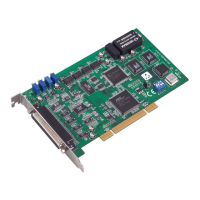
Table 5.18: RS-422 DB9 Pin Assignment
DTE (Male DB-9) Terminal DTE
Pin Signal Pin Signal
1 TxD- 1 RxD-
2 TxD+ 2 RxD+
3RxD+3TxD+
4RxD-4TxD-
5GND5GND
6RTS-6CTS-
7RTS+7CTS+
8CTS+8CTS+