PCI Communication User Manual 14
2.3.3 Mode Selection by Jumper/DIP Settings
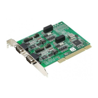
2.3.3.1 RS232/422/485 Selection (PCI-1602B/1602C/1612B/1612C/1622B/1622C)
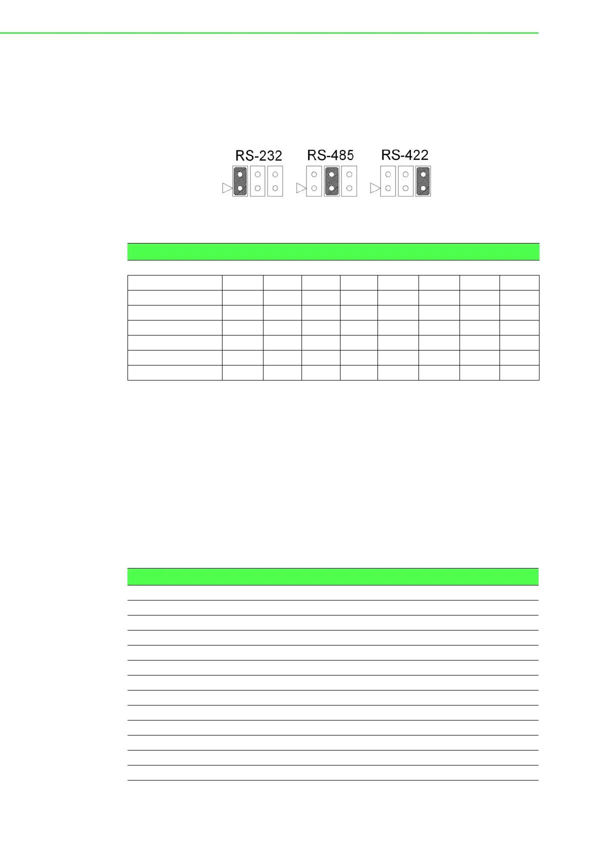
Should you wish to configure the PCI communication card to operate in the RS-232
or RS422/RS-485 mode, you will locate jumpers at CNX to make connection as
shown below.
Figure 2.9 PCI-1600 Series RS-232/422/485 Selection
2.3.3.2 Board ID Function (SW1)
The comm. cards feature a built-in DIP switch for defining the card’s board ID. When
multiple cards are installed, the board ID switch is useful for identifying the device
number of each card.
After setting each COM card, you can identify each card installed in the system
according to their device numbers. The default board ID value is 0 (disabled). To
adjust the board ID value, configure SW1 according to Table 2.2.
After COM ports have been created, the COM port number will be linked to the board
ID even if the card is moved to a different PCI/PCIE slot. This is a useful function for
maintenance and mass production applications.
(PCI-1620A/PCI-1620B/PCI-1622B are SW2)
Table 2.1: PCI-1600 Series Operating Mode Jumper Position
Model CH1 CH2 CH3 CH4 CH5 CH6 CH7 CH8
PCI-1602B CN1 CN3
PCI-1602C CN1 CN3
PCI-1612B CN1 CN2 CN3 CN4
PCI-1612C CN1 CN2 CN3 CN4
PCI-1622B CN10 CN11 CN12 CN13 CN14 CN15 CN16 CN17
PCI-1622C CN1 CN2 CN3 CN4 CN5 CN6 CN7 CN8
PCI-1602UP CN1 CN3
Table 2.2: Board ID Setting
SW Position 3 Position 2 Position 1 Position 0
BoardID BID3 BID2 BID1 BID0
0ONONONON
1ONONONOFF
2ON ON OFF ON
3ON ON OFF OFF
4 ON OFF ON ON
5 ON OFF ON OFF
6ON OFF OFF ON
7 ON OFF OFF OFF
8 OFF ON ON ON
9 OFF ON ON OFF
10 OFF ON OFF ON